Kubernetes Networking Fundamentals: OSI, VXLAN, veth & Linux Bridges
Kubernetes is, at its core, a networking problem wearing an orchestration costume.
Scheduling pods, managing deployments, and scaling replicas are important. However, none of them matter if workloads cannot communicate reliably.
Therefore, before exploring pod networks, CNI plugins, Services, and Network Policies, we need a common networking foundation.
First, we’ll look at the OSI model and the layers that matter for Kubernetes. Next, we’ll explore physical and virtual network appliances. Then, we’ll examine overlay networks. Finally, we’ll see how Linux network namespaces, veth pairs, and bridges make container networking possible..
Why Start With the OSI Model?
The OSI model gets a bad reputation as an academic artifact — seven layers nobody memorizes correctly after their first networking class. But it survives because it’s still the best shared mental model for reasoning about where a problem lives.
For Kubernetes networking specifically, four layers do almost all the work:
- Layer 2 (Data Link) — Ethernet frames, MAC addresses, switching. This is where bridges, VLANs, and the virtual switches inside your hosts operate.
- Layer 3 (Network) — IP addressing and routing. Pod-to-pod communication across nodes, and most CNI plugins, live here.
- Layer 4 (Transport) — TCP/UDP, ports, and load balancing decisions. Kubernetes Services fundamentally operate at this layer (with kube-proxy doing the heavy lifting via iptables or IPVS).
- Layer 7 (Application) — HTTP/gRPC-aware routing. This is where Ingress controllers and service meshes like Istio start to add value beyond what Layer 4 alone can do.
The reason this matters isn’t trivia — it’s diagnostic. When a pod can’t reach a service, “where in the stack is this actually broken?” is the first question, and the OSI model gives you the checklist: Is it DNS (L7)? Is it a Service/kube-proxy issue (L4)? Is it routing between nodes (L3)? Is it the virtual bridge or veth pair (L2)? Skipping this framework is why so much container network troubleshooting turns into random guessing.
Physical and Virtual Network Appliances
Every concept you know from physical networking has a virtual counterpart inside a hypervisor or a Kubernetes node, and understanding the physical version first makes the virtual one click.
Switches forward frames based on MAC addresses within a broadcast domain. In a Kubernetes node, this role is played by a Linux bridge (or an Open vSwitch instance) — a virtual switch living entirely in the kernel, connecting pods on the same host the same way a physical switch connects servers in a rack.
Routers move packets between different IP subnets, using routing tables to decide next hops. In Kubernetes, this is exactly what happens when a pod on Node A talks to a pod on Node B — some component (the CNI plugin, cloud provider routes, or a control-plane-managed route table) has to know how to get a packet from one pod subnet to another.
Firewalls enforce access control based on packet attributes. Physically, this might be a dedicated appliance or a router ACL. In Kubernetes, this maps directly to iptables/nftables rules on each node, and at a higher level of abstraction, to Network Policies — which we’ll cover in depth later in this series.
Load balancers distribute traffic across multiple backend destinations. Physical or virtual load balancers (F5, NSX, cloud LBs) map to Kubernetes Services (ClusterIP/NodePort/LoadBalancer) and Ingress controllers.
The pattern here is consistent: Kubernetes doesn’t invent new networking primitives. It automates and abstracts primitives that have existed in data center networking for decades, and re-implements most of them in software running on each node.
Overlay Networks: Solving the “Too Many Subnets” Problem
Kubernetes wants every pod to have its own routable IP address. However, the physical network should not need a new route for every pod subnet.
This is where overlay networking helps.
An overlay network encapsulates pod traffic inside packets that the underlying network already understands. First, the original pod packet is wrapped inside another packet addressed between Kubernetes nodes.
Next, the underlay network routes that packet normally. Finally, the destination node removes the outer header and delivers the original packet to the pod.
As a result, Kubernetes can provide pod-to-pod connectivity without constantly changing the physical network.
The underlay network only ever sees traffic between node IPs — it has no idea pod subnets exist. Encapsulation and decapsulation happen entirely at the node level.
Container Networking Fundamentals
This is where it all gets implemented. Everything above is context; this is the actual mechanism.
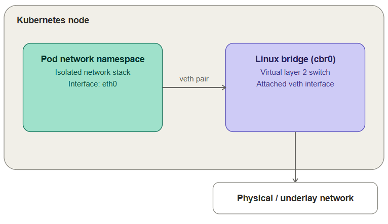
First, the network namespace isolates the pod’s network stack.
Next, a veth pair connects that isolated namespace to the host.
Then, the host-side veth interface connects to a Linux bridge.
Finally, routing or overlay networking carries traffic that needs to leave the node.

Everything above is happening entirely inside one node. The pod never sees the bridge directly — it just has an interface (eth0) that happens to be one end of a pipe terminating on the bridge.
Put together, the flow looks like this: a container generates a packet inside its network namespace → it exits through its side of the veth pair → arrives at the host-side veth end, attached to the bridge → the bridge either switches it directly to another local container, or forwards it out toward the host’s physical/virtual NIC for anything off-host.
In Kubernetes specifically, this whole per-container pattern gets shifted to the pod level — all containers in a pod share a single network namespace (via a pause/sandbox container), which is exactly why containers in the same pod can reach each other over localhost. The CNI plugin’s job, which we’ll dig into in Part 2, is to set up this networking for every pod: allocate an IP, create the veth pair, attach it to the bridge (or an overlay equivalent), and program routes so that pod can be reached from anywhere else in the cluster.
Try It Yourself: Building This by Hand
Everything above is easier to internalize once you’ve built it with your own commands instead of reading about it. This lab reproduces the pod-networking mechanics from scratch on two plain Ubuntu VMs — no Kubernetes, no CNI plugin, just ip commands — so you can see exactly what a CNI plugin is automating for you later in this series.
The topology: each VM gets two network namespaces (standing in for two containers), each connected through a veth pair to a local Linux bridge, with the bridge’s host uplinking through eth0 to a shared physical switch connecting both VMs.
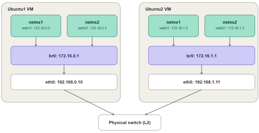
Setup on Ubuntu1 (172.16.0.0/24, eth0: 192.168.0.10)
# Create two network namespaces — these stand in for two containers
sudo ip netns add ns1
sudo ip netns add ns2

# Create the veth pairs. Each pair has one end that stays on the host
# (veth10, veth20) and one end that moves into a namespace (veth11, veth21).
sudo ip link add veth11 type veth peer name veth10
sudo ip link add veth21 type veth peer name veth20

# Move the container-side end of each pair into its namespace
sudo ip link set veth11 netns ns1
sudo ip link set veth21 netns ns2

# Assign an IP to each namespace's interface and bring it up
sudo ip netns exec ns1 ip addr add 172.16.0.2/24 dev veth11
sudo ip netns exec ns1 ip link set veth11 up
sudo ip netns exec ns1 ip link set lo up

sudo ip netns exec ns2 ip addr add 172.16.0.3/24 dev veth21
sudo ip netns exec ns2 ip link set veth21 up
sudo ip netns exec ns2 ip link set lo up

# Create the bridge and give it the .1 address for this subnet
sudo ip link add br0 type bridge
sudo ip addr add 172.16.0.1/24 dev br0
sudo ip link set br0 up

# Attach the host-side veth ends to the bridge and bring them up
sudo ip link set veth10 master br0
sudo ip link set veth20 master br0
sudo ip link set veth10 up
sudo ip link set veth20 up

# Allow the host to forward packets between interfaces
sudo sysctl -w net.ipv4.ip_forward=1
Setup on Ubuntu2 (172.16.1.0/24, eth0: 192.168.1.11)
Identical steps, using the 172.16.1.0/24 addressing from the diagram:
sudo ip netns add ns1
sudo ip netns add ns2

sudo ip link add veth11 type veth peer name veth10
sudo ip link add veth21 type veth peer name veth20

sudo ip link set veth11 netns ns1
sudo ip link set veth21 netns ns2

sudo ip netns exec ns1 ip addr add 172.16.1.2/24 dev veth11
sudo ip netns exec ns1 ip link set veth11 up
sudo ip netns exec ns1 ip link set lo up

sudo ip netns exec ns2 ip addr add 172.16.1.3/24 dev veth21
sudo ip netns exec ns2 ip link set veth21 up
sudo ip netns exec ns2 ip link set lo up

sudo ip link add br0 type bridge
sudo ip addr add 172.16.1.1/24 dev br0
sudo ip link set br0 up

sudo ip link set veth10 master br0
sudo ip link set veth20 master br0
sudo ip link set veth10 up
sudo ip link set veth20 up

sudo sysctl -w net.ipv4.ip_forward=1
Verifying What Works — and What Doesn’t Yet
On Ubuntu1, same-host namespace-to-namespace traffic works immediately, because it never leaves the bridge:
# ns1 reaching the bridge itself
sudo ip netns exec ns1 ping -c 3 172.16.0.1

# ns1 reaching ns2, across the bridge
sudo ip netns exec ns1 ping -c 3 172.16.0.3
Both should succeed — this is Part 1’s namespace/veth/bridge mechanism working exactly as described above, just with real commands instead of a diagram. Now try reaching across VMs:
# From ns1 on Ubuntu1, try to reach ns1 on Ubuntu2
sudo ip netns exec ns1 ping -c 3 172.16.1.2
This one fails, and it’s worth understanding precisely why: Ubuntu1’s kernel has no route for the 172.16.1.0/24 network at all — it only knows about 172.16.0.0/24, the subnet directly attached to its own bridge. Ubuntu1 and Ubuntu2 are on the same physical switch and can reach each other’s eth0 IPs (192.168.0.10 and 192.168.1.11) just fine, but neither host has any idea how to get a packet from its own bridge subnet to the other host’s bridge subnet.
You can fix this by hand, and doing so previews exactly what Part 2’s Flannel host-gw backend automates for you:
# On Ubuntu1: route Ubuntu2's pod subnet via Ubuntu2's eth0
sudo ip route add 172.16.1.0/24 via 192.168.1.11 dev eth0

# On Ubuntu2: route Ubuntu1's pod subnet via Ubuntu1's eth0
sudo ip route add 172.16.0.0/24 via 192.168.0.10 dev eth0
Re-run the cross-VM ping and it should now succeed. What you just did by hand — giving every host a route to every other host’s local pod subnet, using the physical network as the next hop — is precisely the mechanism Flannel’s host-gw backend programs automatically across an entire cluster, and it’s why that backend requires all nodes to sit on the same flat L2 segment: the via address in those routes only resolves if the physical switch can actually deliver an ARP request between 192.168.0.10 and 192.168.1.11 directly, exactly like it just did here.
If you want to see the VXLAN alternative from earlier in this post instead of a flat host-gw route, this same two-VM setup is a reasonable place to hand-build a flannel.1-style VXLAN interface and compare — but that’s a good exercise to attempt on your own once Part 2 has walked through what Flannel automates either way.
Where This Goes Next
With this vocabulary in place — OSI layers as a debugging framework, physical-to-virtual appliance mapping, overlay networking as the answer to “how do all these pods get routable IPs without touching the physical fabric,” and namespaces/veth pairs/bridges as the actual Linux mechanics — the rest of the series builds directly on top of it:
- Part 2: The pod network, the CNI specification, and the Flannel CNI plugin
- Part 3: Calico CNI in depth
- Part 4: Kubernetes Services
- Part 5: Intro to Network Policies
- Part 6: Calico Network Policies
Each of those posts assumes you’re comfortable with everything above. If any of it felt shaky, this is worth a second pass before moving on — nearly every “why can’t this pod reach that service” debugging session eventually traces back to one of these fundamentals.
Conclusion: Building a Strong Kubernetes Networking Foundation
Kubernetes networking becomes much easier to understand once you know what happens beneath the YAML.
First, network namespaces provide isolated networking for pods. Next, veth pairs connect those namespaces to the host. Linux bridges then provide local Layer 2 connectivity.
Meanwhile, routing and overlay technologies such as VXLAN extend communication beyond a single node. As a result, pods can communicate across a Kubernetes cluster while the physical network continues routing normal node traffic.
These Kubernetes networking fundamentals provide the foundation for understanding pod networking, CNI plugins, Services, and Network Policies.
Next in the series, we’ll move from these Linux networking fundamentals to the Kubernetes pod network, CNI specification, and Flannel.
Need Help With Kubernetes and Cloud Infrastructure?
Building a production Kubernetes environment requires more than deploying containers. Networking, security, segmentation, performance, observability, and scalability must work together.
Trezbon helps organizations design, deploy, secure, and optimize Kubernetes, cloud, networking, and enterprise infrastructure.
👉 Discuss your infrastructure requirements with Trezbon:
https://trezbon.com/#contact
NVIDIA GPU Workloads on Kubernetes — Part 8: Building the AI Platform & Application Layer
NVIDIA GPU Workloads on Kubernetes — Part 11: Key Concepts Deep Dive
Kubernetes for AI/ML Workloads: GPU Scheduling & MLOps Guide
About Author

abhishek
Cloud Platform Lead and AI Infrastructure Architect at e& enterprise, with 12+ years in data center, virtualization, security and AI infrastructure. I design and build private cloud and sovereign AI platforms, working with VMware (NSX-T, vSphere, vSAN, HCX, AVS, SRM), Kubernetes, Terraform and GPU inference infrastructure for LLMs. Previously served Networkers Home (CCIE instructor, trained around 50 CCIEs), VCE/EMC2, Cisco, VMware and Arista across TAC, consulting, design and training. Certifications: CCIE#48639 (Data Center and R&S), VCIX-DCV and NV, CKA, NVIDIA AI Infrastructure, Azure Solutions Architect Expert, Terraform Associate, Palo Alto PCNSE. LinkedIn: https://www.linkedin.com/in/abhishekkunal51/