Exploring the Default Behaviour of Interconnected IOS Switches
In this blog, we’ll learn how to understand the default behavior of two interconnected IOS switches. The task requires us to connect two switches, A and B, and two PCs, H1 and H2, to see if they can communicate with each other. Let’s dive into the steps needed to complete this task.
Lab Task
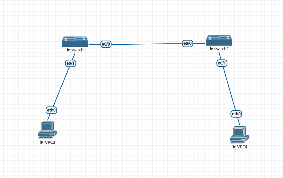
Step 1: Connecting the Switches – To start, connect switch A and switch B with one link. This link will allow communication between the two switches.
Step 2: Connecting the PCs – Next, connect two PCs, H1 and H2, to each switch. These PCs will serve as our test hosts for communication between the switches.
Step 3: Configuring the PCs – Now, configure the H1 and H2 interfaces as L3 interfaces with IP addresses from the same subnet. This configuration will allow the PCs to communicate with each other using IP addresses.
Step 4: No Configuration in Switches For this task, we will not perform any configuration in the switches. We want to see what happens when two switches are connected without any specific configuration.
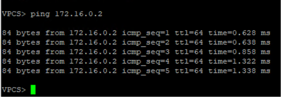
Step 5: Testing Communication Finally, check if H1 and H2 are able to ping each other.
Step 6: Reasoning with Evidence In case the communication fails or succeeds, we need to reason the failure/success with packet capture evidence.
By following these steps, we can explore the default behavior of interconnected IOS switches and understand the communication between the switches and PCs. Whether it’s for upskilling your knowledge or troubleshooting network issues, this task is a great starting point for anyone looking to learn more about IOS switches.
Analysis Of The Lab Task
- Communication Success: Our first finding was that the two hosts, H1 and H2, were able to ping each other. This means that the communication between the switches and PCs was successful, and the hosts were able to exchange data packets.
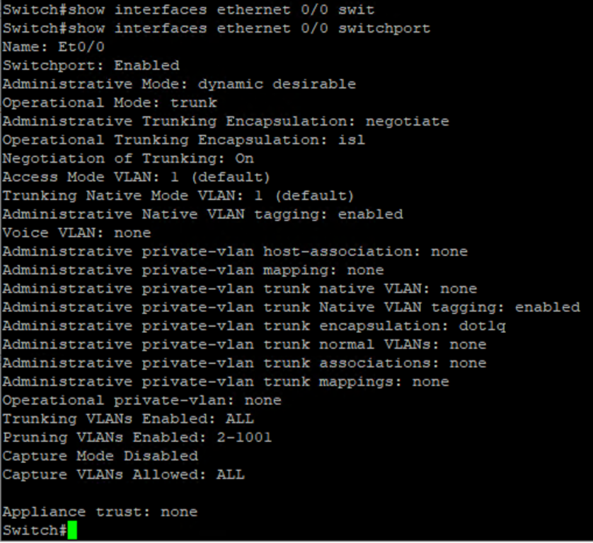
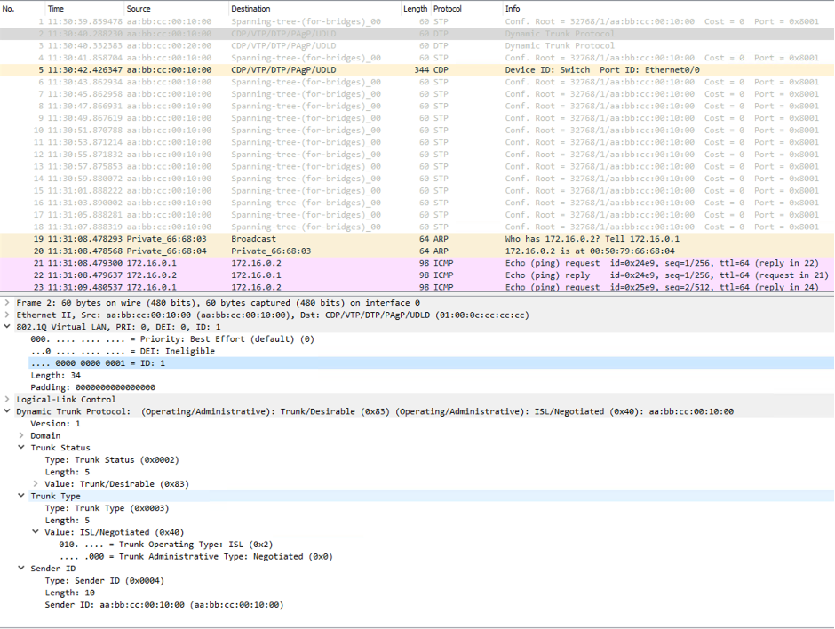
- ISL Encapsulation: The packet capture from the source side exit interface showed that the Dynamic Trunking Protocol (DTP) had chosen the Inter-Switch Link (ISL) as the encapsulation technique and set the interface type as a trunk.
- Trunk Mode: Analysing the destination side, we found that it was also similar, with encapsulation type ISL and the interface in trunk mode.
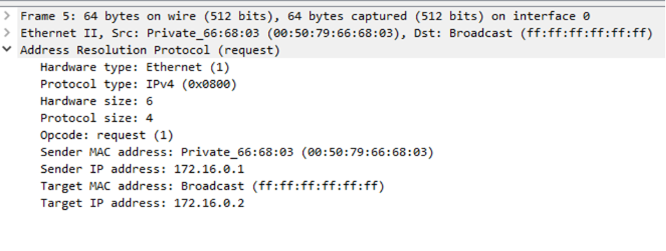
- ARP Broadcast: Since the interfaces on both sides were trunk ports and the allowed VLANs were set to all, the ARP broadcast request was able to traverse from the source switch interface to the destination switch.
- 802.1Q Tagging: The 802.1Q tagging ID was set to 1, which is the native VLAN ID, on both sides.
- Spanning Tree Messages: We observed that Spanning Tree messages were sent every 2 seconds.
- CDP Protocol: The Cisco Discovery Protocol (CDP) was sent every 60 seconds.
- Spanning Tree Multicast MAC Address: The Spanning Tree Multicast MAC address was 01:80:c2:00:00:00.
- CDP Multicast MAC Address: The CDP Multicast MAC address was 01:00:0c:cc:cc:cc.
- DTP Multicast MAC Address: The Dynamic Trunking Protocol (DTP) was also using the same multicast MAC address as the CDP, which was 01:00:0c:cc:cc:cc.
Packet Capture and CLI Outputs
Ping to destination host
ARP Broadcast Request
ARP response with destination MAC address
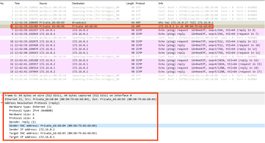
The system acts as a single broadcast domain, the ARP broadcast message has reached the destination target and the target responded with its MAC address.
Destination MAC address
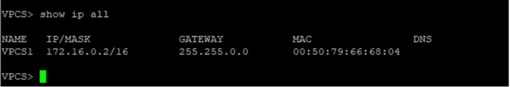
Default Switchport Configuration of the source side host
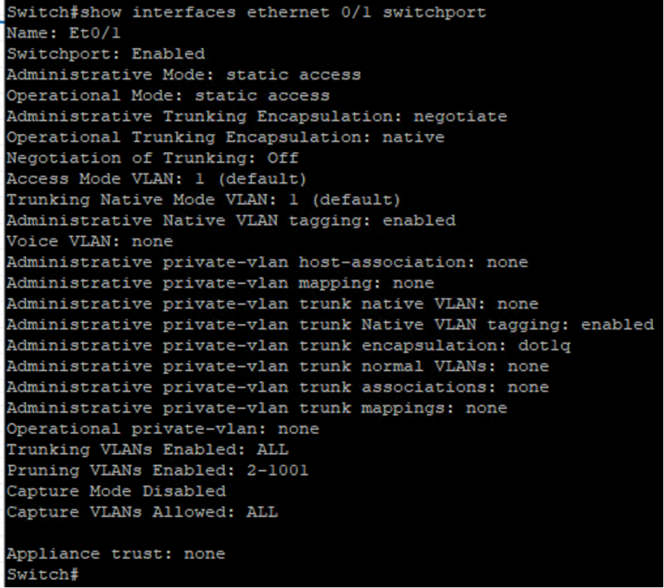
Default Switchport Configuration of the Source Switch Exit interface
Packet Capture From The Source Switch Exit Interface
In conclusion, our findings from this task provide valuable insights into the default behavior of interconnected IOS switches. By understanding the communication between the switches and PCs, and the protocols and mechanisms used, we can better manage and troubleshoot network issues.
Related Topic: https://www.networkbachelor.com/network-ping-explained/
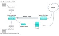
Cisco Guest Wi-Fi Traffic Tunneling

Cisco UCCX(Contact Center) Administration and Scripting Series
Wireless Standards and Cisco Solutions
About Author
Anas Hira
Anas Hira is an entrepreneur and innovator focused on the network programming and IT services space. Anas has focused on network programming and developed many programs to ease network operations and delivery. He is a certified RHCE and has certification on Cisco routing and switching domain as well. Over the years Anas has developed immense troubleshooting & configuration experience on the domain such as Collaboration and Server virtualization.