Exploring the Impact of Dynamic Trunking Protocol (DTP) and VLAN on Interconnected IOS Switches
In this post, we’ll dive into understand how Dynamic Trunking Protocol (DTP) affects communication between interconnected IOS switches. We’ll perform several tasks and observe the behaviour of PCs, switches, and the ping frames sent and received between them.
Task 1: Disabling DTP
In this task, we’ll disable DTP on one switch and observe the behaviour of PC1 and PC2. We’ll perform packet capture and analyse the frames sent and received between the switches to understand the difference between when DTP is enabled and disabled.
Task 2: Disabling DTP
In this task, we’ll disable DTP on both switches and observe the behaviour of PC1 and PC2. We’ll perform packet capture and analyse the frames sent and received between the switches to understand the difference between when DTP is enabled and disabled.
Task 3: Different VLANs on each switch
In this task, we’ll assign one VLAN to all the interfaces of one switch and another VLAN to all the interfaces of the other switch and observe the behaviour of PC1 and PC2. We’ll again perform packet capture and analyse the frames sent and received between the switches to understand the impact of different VLANs on communication.
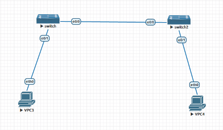
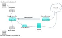
Topology
Behaviour of Switchport
Understanding switch ports and how they function is a fundamental concept in networking. A switch port is a physical connection point on a network switch that connects network devices. Each switch port can be configured in different modes depending on the intended use of the port. We will explore some of the common switch port modes and their functionalities.
Switchport Mode Trunk
The switchport mode trunk is a configuration that tells the switchport to always function as a trunk port. It means that the port will only transmit and receive tagged frames. Additionally, the switchport will send Dynamic Trunking Protocol (DTP) frames to negotiate a trunk with the other end. If the other end supports the trunk negotiation, then the two ports will establish a trunk link. If not, the port will remain as a trunk port.
Switchport Nonegotiate
The switchport nonegotiate configuration disables DTP negotiation on the port. It means that the port will not send or respond to DTP frames, and all DTP negotiations will be disabled. This configuration is useful when you want to ensure that a port is always configured as either an access or trunk port without any negotiation.
Switchport Mode Dynamic Desirable
The switchport mode dynamic desirable configuration is similar to the trunk configuration. The port will send DTP frames to negotiate a trunk link with the other end. However, if the negotiation fails, the port will become an access port. It means that the port can be either a trunk or an access port, depending on the negotiation with the other end.
Switchport Mode Dynamic Auto
The switchport mode dynamic auto configuration is a passive configuration that waits for the other end to initiate DTP negotiation. If the other end asks the port to become a trunk, the port will become a trunk port. If the other end does not initiate any negotiation, the port will become an access port.
Switchport Mode Access
The switchport mode access configuration is a mode that tells the port never to function as a trunk port. The port will always send and receive untagged frames and will not send any DTP frames. This configuration is useful for end devices such as computers, printers, and servers.
Switchport Trunk Encapsulation
The switchport trunk encapsulation configuration is used to specify the trunking protocol used on the port. It means that the port will not negotiate the trunking protocol using DTP frames. Instead, it will only use the protocol specified in the configuration.
Disabling DTP on both switches
DTP can be disabled on switches either by inputting the command “switchport nonegotiate” or by changing the switchport mode to access
Test 1:
Changed the switchport configuration of ethernet 0/0 of switch 1 to access port, effectively disabling DTP on that port. We kept DTP enabled on ethernet 0/0 of switch 2. We then tested the connectivity between VPC3 and VPC4 by sending a ping request from VPC3 to VPC4.
No explicit VLAN configuration on switch 1 and switch 2(Default VLAN=1).
Result:
The ping request from VPC3 to VPC4 was successful. This means that the two virtual PCs were able to communicate with each other despite the changes we made to the switchport configurations.
Reason:
When we disabled DTP on switch 1’s ethernet 0/0 port by changing its operational mode to “static access”, the negotiation of trunking was turned off. This means that the port will no longer try to negotiate with the neighbouring switch to become a trunk port. Instead, it will remain in access mode and will only carry traffic for a single VLAN. As we did not change anything in the switch 2 side configuration, the administrative mode of the switchport remained dynamic desirable, which caused it to try to negotiate a trunk port with switch 1. However, since switch 1 was administratively configured for static access mode, the negotiation failed, and DTP made its native port an access port. This resulted in successful pings from VPC3 to VPC4, as the two hosts were now in the same VLAN.
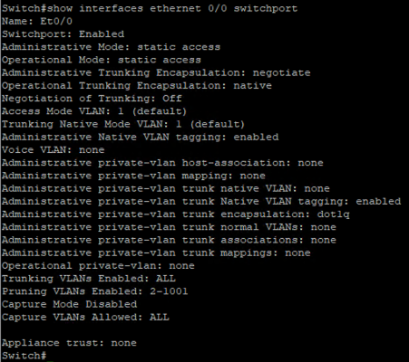
Screenshot of the source side switch exit interface
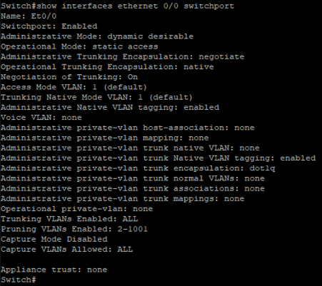
Screenshot of the destination side switch exit interface
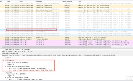
After taking the packet capture from the source side switch exit interface, it is evident that the switchport is sending only STP and CDP packets and not DTP signals.
Packet Capture from source side switch exit interface
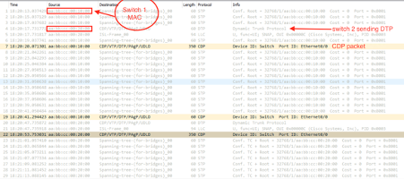
Switch 2 sends DTP packets, however, switch 1 does not respond to them as the DTP is disabled.
Then switch sends the CDP packet with native VLAN ID information and subsequently switch 1 sends the CDP packet with native VLAN information and finally switch 2 sets its switchport type to access mode, see the screenshot for reference
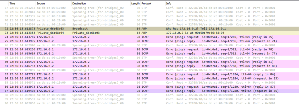
Source side switch exit interface PCAP screenshot
Both switchport ethernet 0/0 of switch 1 and switch are in the same VLAN, so the ARP broadcast traverses the switch and reaches the destination host and thus ping output is successful.
Test 2:
Changing the switchport configuration of ethernet 0/0 of switch 2 to access port making the DTP state to disabled.
Result:
Ping worked between hosts without fail
Reason:
After changing the switchport configuration of Ethernet 0/0 on switch 2 to an access port with DTP disabled, both switchports were in access mode with VLAN ID 1. Through the Cisco Discovery Protocol (CDP) protocol, both switches exchanged native VLAN information.
When the hosts sent untagged packets, switch 1 received the frame and added its native VLAN ID of 1 to the frame. The switch then determined that the frame needed to be sent out to another interface using the Address Resolution Protocol (ARP) technique. The exit interface was also an untagged port, so the tag was removed, and the frame was sent out.
The destination switch’s ingress interface received the untagged frame, added its native VLAN tag, and relayed the ARP request to its broadcast domain, which reached the destination host.
Test 3
Changing the switchport configuration of all switchport of switch 1 to access VLAN 10 and all interfaces of switch 2 to access VLAN 20 and making the DTP state to disabled.
Result:
Ping is Successful
Reason:
Once the switch receives an untagged from its host it marks the native VLAN ID of the receiving switchport to its tag field which in this case is VLAN 10 and does an ARP request in VLAN 10 broadcast domain, it reaches the egress port of the switch 1 (ethernet 0/0) and leaving the egress port it removes the VLAN tag from it, now the ingress port of the switch 2 receives the untagged frame and tags its native VLAN ID to it which is VLAN 20 in this case and relay the ARP broadcast to its broadcast domain and reaches the destination.
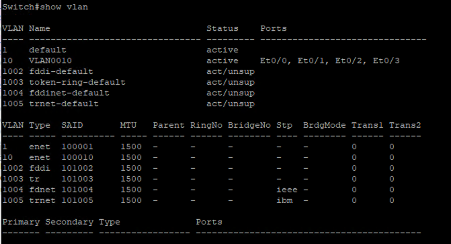
Interface VLAN information on switch 1
Switch Notifying the VLAN Mismatch

Packet Capture Screenshot from ingress interface of switch 2
Conclusion
VLAN configuration plays a crucial role in network management and DTP helps the switch dynamically configure its switchport depending on the directly connected neighbour switch port configuration. By testing different scenarios, we can determine the impact of different VLAN configurations and understand how the network behaves when DTP is disabled/enabled.
Related Links

Cisco UCCX(Contact Center) Administration and Scripting Series
Cisco Guest Wi-Fi Traffic Tunneling

Wireless Standards and Cisco Solutions
About Author
Anas Hira
Anas Hira is an entrepreneur and innovator focused on the network programming and IT services space. Anas has focused on network programming and developed many programs to ease network operations and delivery. He is a certified RHCE and has certification on Cisco routing and switching domain as well. Over the years Anas has developed immense troubleshooting & configuration experience on the domain such as Collaboration and Server virtualization.