Network Ping Command Explained
Network Ping Command explained with packet tracer
Ping is the software utility to test the reachability of a host in a network, it is crucial for a network engineer to know how ping works in a real network. Here I’m explaining the Network ping command flow in a simple network which I have tested and verified using network simulation tool – Cisco packet tracer.
Mainly our focus is on how the packet is traversing through the devices and what modifications are made on packets to reach the destination.
Scenario: PC 1 and PC 2 are in different IP subnet.
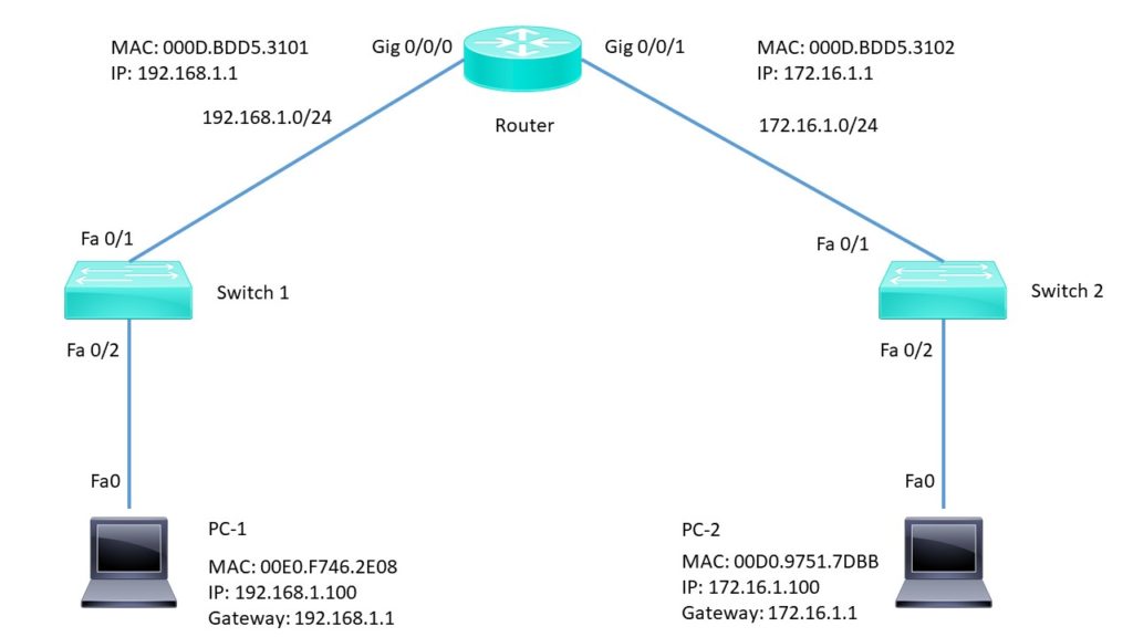
The complete traffic flow will be explained in the 5 step process:
Step 1: PC 1 Initiating Network ping command
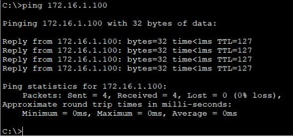
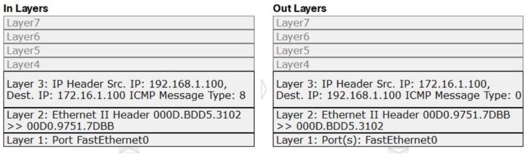
Ping operates at layer 3 of the OSI layer, it initiates an ICMP echo request and sent it to lower process.
1> Since the source IP address is not specified in the command, the device sets its IP as the source IP address.
2>The destination IP address 172.16.1.100 is not in the same subnet and is not the broadcast address, so the device Sets the next-hop to the default gateway address
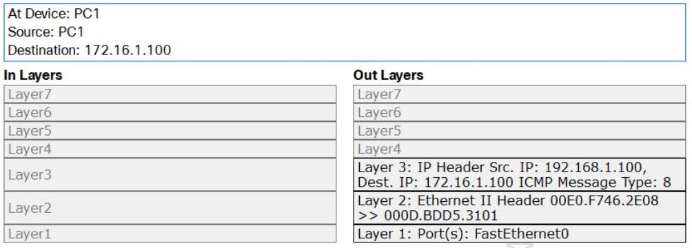
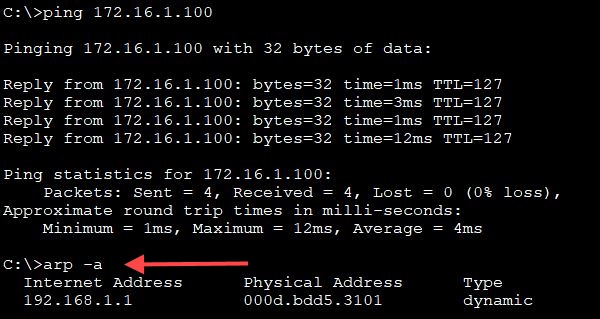
3> since the next gateway MAC address is not in the ARP table of the PC, it initiates an ARP request for the same. Once it receives the MAC address of the gateway through ARP response, it sets the frame’s destination MAC address field to the one it received from the ARP response.
4> PC encapsulates router’s MAC address into the Ethernet frame
5> PC network adaptor sends out the frame.
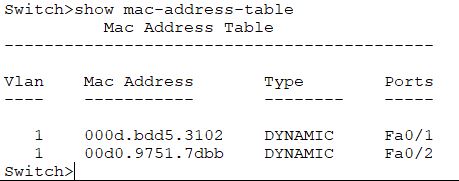
Step 2: At Switch 1
1> Fa 0/2 receives the frame
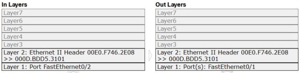
2> Frame source MAC address is found in the MAC table of the switch
3> This is unicast frame, the switch looks its MAC table for the destination MAC address, and sends the frame to the port associated with the destination MAC address.
Note: Broadcast Frame address: FFFF:FFFF:FFFF
4> Here switch sends the frame to out port Fa 0/1
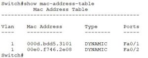
Step 3: At Router
1> Gig 0/0/0 receives the frame
2> Frame destination MAC address matches the receiving port’s MAC address
3> Device de-encapsulates the PDU from the Ethernet frame
4> Device looks up the destination IP address in the routing table
5> Routing table has the entry for destination IP address, router decrements the TTL on the packet
6> Router sets the frame’s destination MAC address to the MAC address of the PC2, here router uses the ARP to get the MAC address of the PC 2.
7> Router Encapsulates the PC2 MAC address to Ethernet frame
8> Gig 0/0/1 sends out the frame
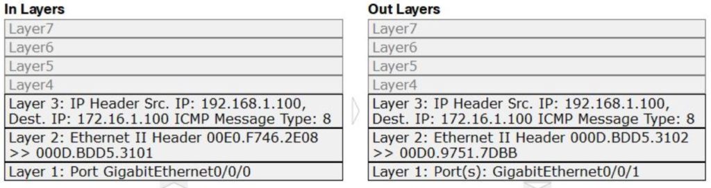
Step 4: At Switch 2
1> Fa 0/1 receives the frame
2> Frame source MAC address was found in the MAC table of the switch
3> This is a unicast frame, switch looks in its MAC table for the destination MAC address
4> Switch sends the frame out that port
Step 5: At PC 2
1> Fast Ethernet 0 receives the frame.
2> The destination MAC address matches the receiving port’s MAC address
3> Device de-encapsulates the PDU from the Ethernet frame
4> Packet’s destination IP address matches the device’s IP address
5> Packet is an ICMP packet
6> ICMP process received an echo request message
7> ICMP process the replies to the echo request by setting ICMP type to echo reply as ping is an iterative process.
8> ICMP sends the echo reply
9> Destination address is set to 192.168.1.00.
By default, ping sends 4 ICMP packets. the first ICMP packet requires ARP to identify the destination MAC address, the remaining 3 ICMP packet does not require ARP.
Exploring the Impact of Dynamic Trunking Protocol (DTP) and VLAN on Interconnected IOS Switches
Exploring the Default Behaviour of Interconnected IOS Switches

Cisco UCCX(Contact Center) Administration and Scripting Series
About Author
Anas Hira
Anas Hira is an entrepreneur and innovator focused on the network programming and IT services space. Anas has focused on network programming and developed many programs to ease network operations and delivery. He is a certified RHCE and has certification on Cisco routing and switching domain as well. Over the years Anas has developed immense troubleshooting & configuration experience on the domain such as Collaboration and Server virtualization.
Nice article, useful to understand the overall ping traffic flow between two different subnets
Thanks Robert.
Glad you liked it.
Awesome! Welcome to the Club!
Nice article explained from the basis level
Well explained…nice bro..
bravo anas
bien expliqué
Nice explanation, how pc1 will understand the pc2 is in different subnet?