Bare Metal GPU Cloud for NVIDIA DGX SuperPOD: vMetal Workbook
A hands-on training guide for infrastructure engineers
How do you turn NVIDIA DGX hardware into a secure, self-service bare metal GPU cloud for multiple tenants?
Racking DGX servers is only the beginning. Next, you need to provision operating systems, create Kubernetes clusters, isolate tenant networks, assign physical GPU nodes, and schedule AI workloads.
More importantly, all of this must happen without requiring an engineer to manually configure a server every time a tenant needs GPU capacity.
This hands-on vMetal workbook explains how those pieces fit together.
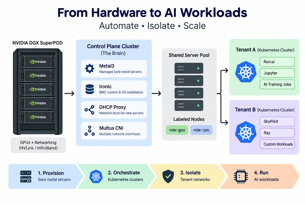
First, we explore bare-metal provisioning with Metal3 and Ironic. Next, we examine Kubernetes-based tenant isolation and network segmentation. First, we explore how physical GPU infrastructure is managed and prepared for tenant use.
Next, we examine how automated provisioning connects bare-metal servers to Kubernetes environments.
Then, we follow the lifecycle of a physical GPU server as it moves from a shared management pool into an isolated tenant environment.
At the same time, network isolation ensures that each tenant receives a separate and secure environment.
As a result, GPU resources can be assigned dynamically while maintaining clear tenant boundaries.
Finally, we launch a GPU workload and follow the complete process—from a pending request to a provisioned DGX node running inside the tenant’s Kubernetes cluster.
In this way, the workbook connects each infrastructure component to the complete GPU provisioning workflow.
By the end, you’ll understand how bare-metal GPU infrastructure can support automated provisioning, tenant isolation, dynamic GPU capacity, and self-service AI workloads.
Module 0: The Problem — Why This Exists
You’ve racked the DGX nodes. NVLink is cabled. InfiniBand is up.
Power is on.
Now what?
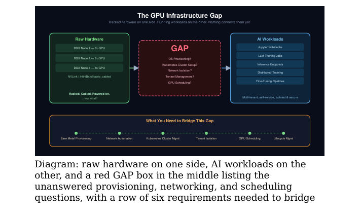
That’s the gap nobody puts on the datasheet. A DGX SuperPOD starts as raw infrastructure: GPUs, NICs, and a high-performance fabric. However, organizations still need a way to turn that hardware into an isolated, self-service environment for AI workloads.
Moving from “racked and powered on” to engineers running Jupyter notebooks and training jobs requires solving five core infrastructure challenges:
- OS provisioning: How does a bare-metal server receive an operating system without someone manually installing it?
- Kubernetes cluster setup: How does a newly provisioned server automatically join the correct Kubernetes cluster?
- Network isolation: How do you ensure Tenant A cannot access Tenant B’s network traffic?
- Tenant management: How do you assign a server to one tenant, reclaim it, and then safely assign it to another?
- GPU scheduling: How are AI workloads matched with available GPU resources?
Individually, these capabilities may not appear in a GPU benchmark. However, together they determine how efficiently a GPU cloud can provision infrastructure and make expensive GPU capacity available to users.
Therefore, building a successful bare-metal GPU cloud requires more than powerful hardware. It also requires automated provisioning, Kubernetes orchestration, secure tenant isolation, and intelligent GPU scheduling.
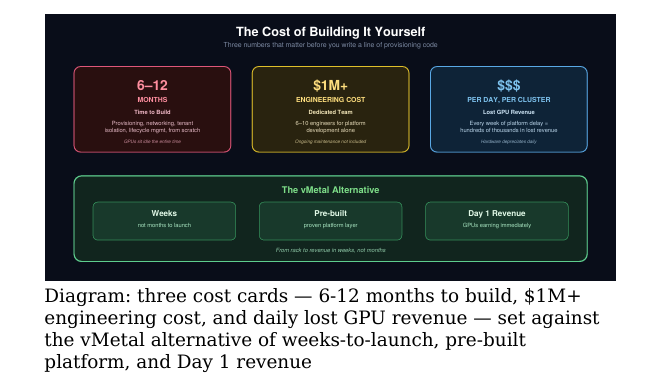
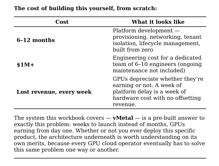
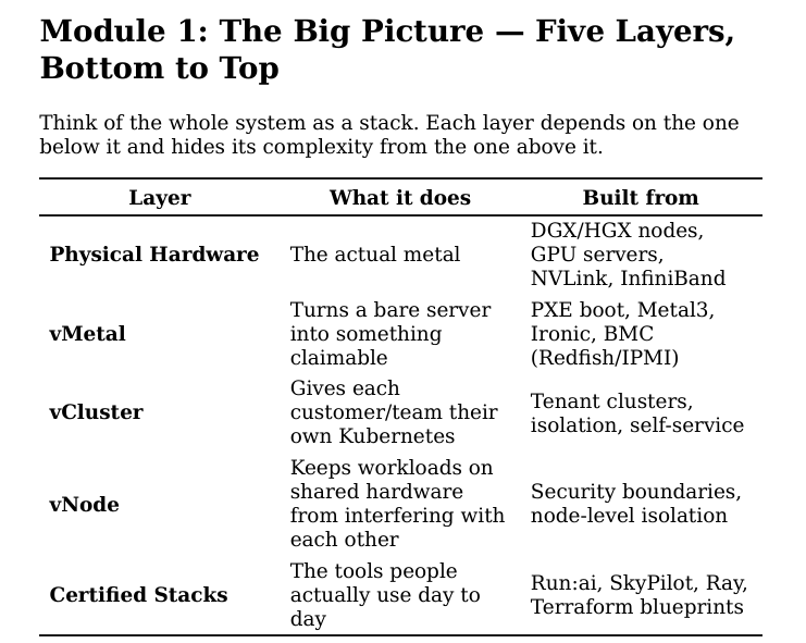
BMC (Baseboard Management Controller): A small,
independent computer built into every server that lets you
power it on/off, watch boot logs, and mount virtual media — all
remotely, even if the main OS is dead or not installed yet. This is
how “provisioning” happens without a human standing at the
rack.
Hypervisor: Software that sits between physical hardware and
virtual machines, letting one physical server pretend to be
several. VMware ESXi is the classic example.
The single most important architectural decision in this whole system:
there is no hypervisor anywhere. Every workload gets to talk to the
physical GPU directly. You give up some conveniences you’d get from
a VMware-style hypervisor (live migration, easy snapshotting) in
exchange for zero performance tax — and when the GPU is the
expensive, scarce resource, even a small overhead tax is real money
at scale.
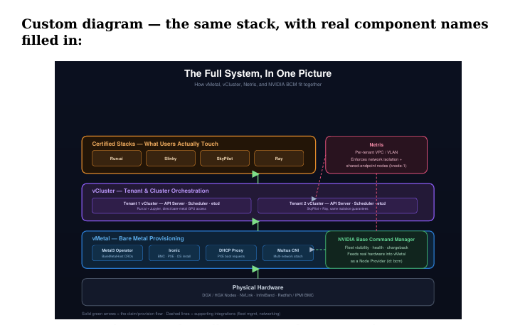
Custom diagram: the full system architecture, showing
Metal3/Ironic and NVIDIA BCM at the vMetal layer, per
tenant vClusters with Netris handling network isolation, and
Certified Stacks (Run:ai, Slinky, SkyPilot, Ray) at the top.
This is the diagram to keep open in a tab while reading the rest of this
workbook — every module below zooms into one box or one arrow
from this picture. vMetal is the foundation layer — it answers the
question “how does a bare server become something a tenant can
actually claim and use?” That’s what the rest of this workbook is
about.
Module 2: vMetal — What’s Actually
Running Underneath
vMetal is built from two well-known open-source projects, not a
proprietary black box:
Metal3: A Kubernetes operator (a piece of software that
manages other things using Kubernetes-style rules) that
represents each physical server as an object Kubernetes can
track and act on.
Ironic: The actual engine that does the provisioning work —
powers a server on via its BMC, boots it over the network, and
writes an operating system to its disk. Originally built for
OpenStack, now widely reused elsewhere.
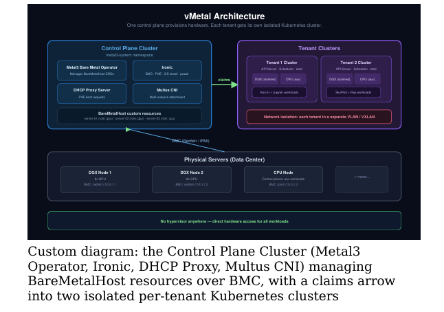
Put together, there are two moving pieces: the Control Plane Cluster and the Tenant Clusters.
The Control Plane Cluster
The Control Plane Cluster acts as the brain of the platform. It runs the core services responsible for managing, provisioning, and connecting physical servers.
- Metal3 Bare Metal Operator — Tracks every physical server as a BareMetalHost object. We cover this in more detail in Module 4.
- Ironic — Handles BMC control, network boot, and operating system installation.
- DHCP Proxy Server — Provides network-boot instructions to servers that do not yet have an operating system.
- Multus CNI — Allows a Kubernetes node to use multiple network interfaces. For example, a node can have both a management connection and a tenant-facing connection.
Together, these components automate the lifecycle of bare-metal servers and prepare them for assignment to tenant environments.
The Tenant Clusters
Next, the Tenant Clusters provide isolated Kubernetes environments for customers. Each tenant receives its own Kubernetes control plane, including the API server, scheduler, and etcd.
Tenant clusters can also claim nodes from the shared server pool as capacity is required.
In addition, each tenant can run its preferred AI and GPU tools. For example, one tenant might use Run:ai and Jupyter, while another might use SkyPilot and Ray.
How Physical Servers Are Assigned
Every physical server is labeled according to its role, such as role: gpu or role: cpu.
As a result, the platform can match available physical servers with the requirements of each tenant. This labeling mechanism helps automate node selection and supports efficient allocation of CPU and GPU infrastructure.
Dynamic Node Assignment: How a Server Actually
Moves Between Tenants
Here’s the part that makes “hard tenant isolation” real instead of just
a diagram claim.
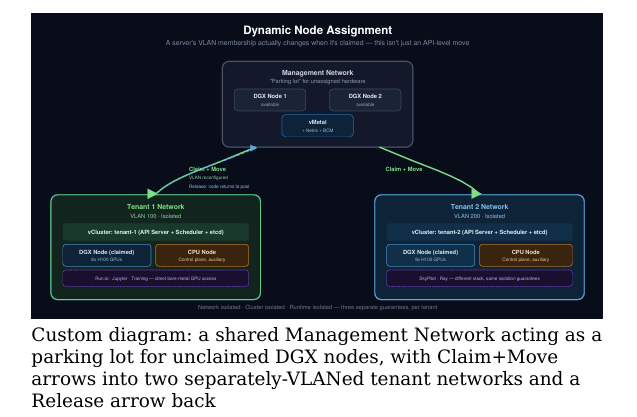
There’s one shared Management Network that acts like a parking
lot for hardware nobody’s using yet — DGX nodes sitting there labeled
available, alongside the vMetal control stack itself.
From there, a server moves one of two ways:
Claim + Move — a tenant claims a node. The system doesn’t just
hand over API access to it — it actually reconfigures the network
so the server’s VLAN membership changes, moving it physically off
the management network and into that tenant’s isolated network
(e.g., Tenant 1 on VLAN 100, Tenant 2 on VLAN 200).
Release — when the tenant is done, the server goes back to the
management pool, network reconfigured back to its original state,
ready for the next claim.
Each tenant ends up isolated three separate ways at once:
- Network isolated — separate VLAN
- Cluster isolated — separate Kubernetes control plane (via
vCluster) - Runtime isolated — direct bare-metal GPU access, no shared
hypervisor kernel to worry about
We’ll watch this actually happen, live, in Module 9.
Module 3: Tenant Network Isolation in
Practice
Before diving into the mechanics of provisioning, it’s worth seeing
what “separate VLAN” looks like on an actual network controller.
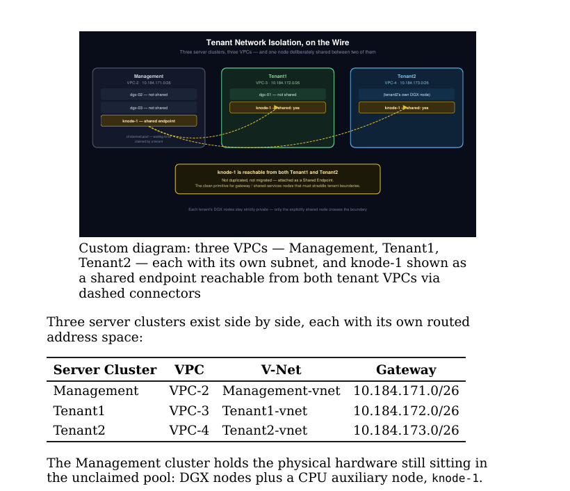
The interesting detail is how knode-1 is exposed once tenants are
active. It isn’t duplicated or migrated between tenants — it’s attached
to both Tenant1 and Tenant2 as a shared endpoint. That’s a
deliberate pattern for shared-services or gateway functions — a node
that needs to be reachable from multiple tenant networks without
being fully joined to either one, which is cleaner than the alternative
of giving one tenant a routed path into another’s VPC, or duplicating
the node outright.
Module 4: The Server Lifecycle — A State
Machine You Should Memorize
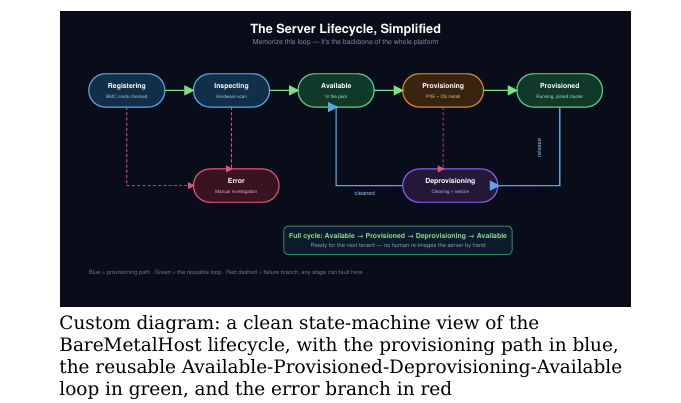
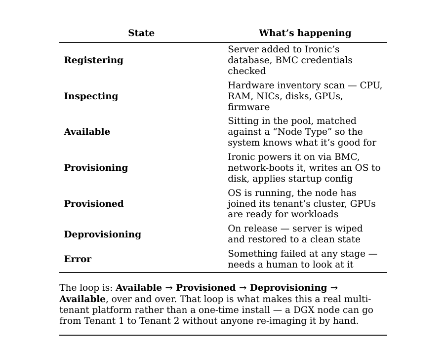
Every physical server moves through a fixed set of states. This is the
backbone of the whole system, and once you know it, everything else
in this workbook makes more sense.
Module 5: The Six Steps of Provisioning a
Node
When a tenant cluster asks for a node, here’s exactly what happens
behind the scenes:
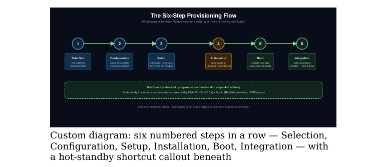
- Selection — the system finds an available server matching the
requested hardware profile (via the label matching from Module 2) - Configuration — startup instructions (called “cloud-init userdata”
— a standard way of telling a fresh Linux install what to do on first
boot) are generated and stored securely - Setup — the OS image and startup instructions are attached to the
server’s record — this single step is what triggers everything
downstream - Installation — power on via BMC → network boot → an installer
writes the OS to disk - Boot — server reboots into its real OS and runs the startup
instructions - Integration — startup scripts automatically register the node with
its tenant’s Kubernetes cluster — no human touches it
Speed trick worth knowing: a pool of hot standby nodes — pre
provisioned and just waiting — can skip steps 4 and 5 entirely. Instead
of minutes, a tenant gets a ready node in seconds. If tenants are
bursting in and out of capacity, that pre-provisioned buffer is the
difference between “demo” and “product.”
Module 6: Configuration as Code (Read
This Even If You Don’t Write YAML Daily)
Everything here is standard Kubernetes YAML, which means your
existing GitOps tooling (ArgoCD, Flux) already knows how to manage
it — no special deployment process needed.
CRD (Custom Resource Definition): Kubernetes lets you
invent your own object types beyond the built-ins (Pods,
Services, etc.). BareMetalHost is a custom resource — Kubernetes
doesn’t know natively what a physical server is, but Metal3
taught it to.
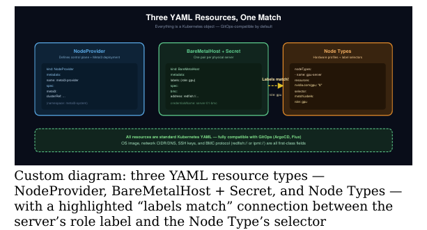
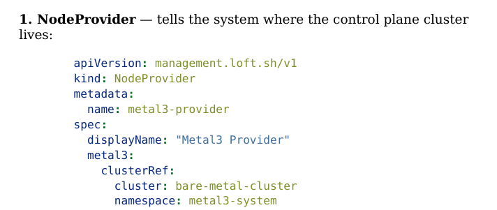
Three resource types do all the work:
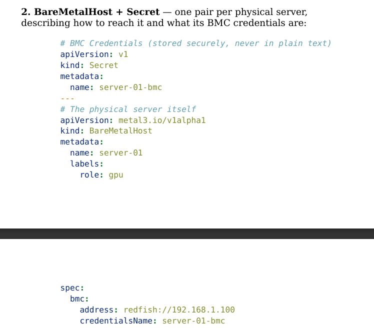
Redfish vs IPMI: both are protocols for remotely controlling a
server’s BMC. Redfish is newer and preferred; IPMI is older but
still common on existing data center hardware. vMetal supports
both.
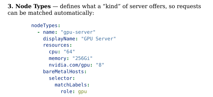
The matching logic is nothing exotic: role: gpu on the server matches
matchLabels: role: gpu on the Node Type. That’s the entire
mechanism behind “Selection” in Module 5’s six-step flow.
Module 7: Who Should Actually Use This
This isn’t only for hyperscaler-scale operators.
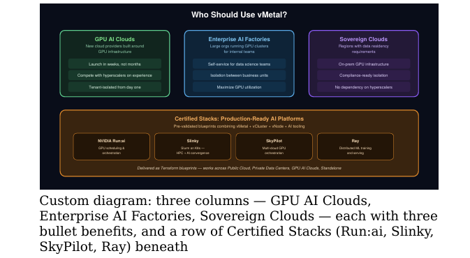
Three distinct groups get value out of the same architecture:
| Who | Why it fits |
| GPU AI Clouds | New cloud providers built around GPU infrastructure — need to launch in weeks not months, compete with hyperscalers on experience, and be tenant-isolated from day one |
| Enterprise AI Factories | Large orgs running internal GPU clusters for multiple teams — need self-service for data science teams, isolation between business units, and to maximize GPU utilization instead of letting it sit idle |
| Sovereign Clouds | Regions or organizations with data residency requirements — need on-prem GPU infrastructure, compliance-ready isolation, and zero dependency on hyperscalers |
On top of the base platform sit Certified Stacks — pre-validated,
production-ready combinations of vMetal + vCluster + vNode + a
specific AI tool, delivered as version-controlled Terraform blueprints:
NVIDIA Run:ai — GPU scheduling and orchestration, with
fairness and isolation guarantees
Slinky — NVIDIA’s take on running Slurm (the classic HPC
scheduler) on Kubernetes, for HPC/AI convergence
SkyPilot — multi-cloud GPU orchestration with workload
portability and cost optimization
Ray — distributed computing for ML training and serving at scale
All of it is designed to work the same way across public cloud, private
data centers, GPU-native clouds, or standalone deployments — the
same YAML, the same lifecycle, regardless of where the metal actually
sits.
Module 8: Hands-On Walkthrough, Part 1
— Standing Up a Tenant Cluster
Time to see the YAML from Module 6 turn into a real, running cluster.
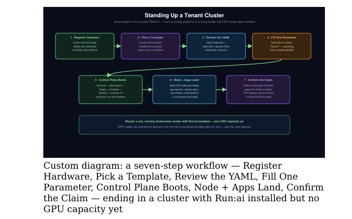
Step 1 — Register the hardware source. Before creating anything,
the platform needs a Node Provider pointed at where servers
actually come from — in this case a provider named bcm, connection
type Nvidia BCM (the same NVIDIA Base Command Manager fleet
tool referenced in Module 7), talking to the BCM API over a
credentialed endpoint via a Kubernetes secret. Each Node Provider
also defines its Node Types — the same concept from Module 6,
editable as a form instead of raw YAML.
Step 2 — Start from a template, not a blank cluster. Creating a
virtual cluster doesn’t drop you into raw YAML — you pick a
Template first. This environment has one: Tenant Virtual Cluster.
Templates are how a platform team encodes “this is what a compliant
tenant cluster looks like” once, so nobody downstream has to hand
wire networking or node providers themselves.
Step 3 — Look at what the template actually generates.
Selecting the template opens a config screen with the generated
vcluster.yaml shown read-only on the side. Two blocks matter most:
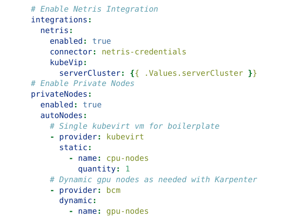
Two things are worth noticing here. First, the tenant’s networking is
wired straight to Netris — the same VPC/VLAN mechanism from
Module 3 — instead of leaving it to whoever fills out the form to get
right. Second, there are two very different kinds of auto-provisioned
nodes: a small, always-present static VM (running on KubeVirt, a
lightweight VM-on-Kubernetes technology) for the CPU/control-plane
role, and a dynamic pool of real bare-metal GPU nodes from BCM,
provisioned on demand — the Kubernetes equivalent of “Karpenter,” a
well-known pattern for scaling node pools automatically based on
actual demand rather than pre-allocating everything up front.
Why a VM for the CPU node in a “no hypervisor” system?
Because that node never touches a GPU workload — it just runs
lightweight control-plane and auxiliary services. It’s fine to be a
VM. The GPU capacity itself, where performance actually
matters, stays on bare metal.
Step 4 — Fill in the one thing the template leaves open. The
form only asks for what the template didn’t already decide: a single
required field, Netris Server Cluster — “the netris server cluster to
use for the vCluster; the control plane as well as all nodes will be part
of that server cluster.” Set the name to tenant1, the Netris Server
Cluster to Tenant1, hit Create.
Step 5 — Watch the control plane come up. The new cluster starts
through a visible five-step sequence: Scheduling Control Plane →
Creating Namespace → Deploying Control Plane → Control Plane
Available → Connecting to Platform. This happens in seconds, not
minutes, because — unlike a physical GPU server — the tenant’s
control-plane components are just containers running on the existing
host cluster, not new hardware being provisioned.
Step 6 — Confirm the node and apps landed. A short while later,
tenant1 shows Running, with one joined node — the static kubevirt
VM, role Worker, status Ready. Its Apps tab shows a set of Helm
releases installed automatically, with no manual commands: gpu
operator, ingress-nginx, kube-prometheus-stack, runai-backend, runai
cluster. That last pair confirms Run:ai really does get bootstrapped
straight into a fresh tenant cluster as part of creation — not a
separate manual install step.
Step 7 — Confirm the claim on the provider side. Back on the
platform-wide Nodes view, the Node Providers now show real
counters: bcm shows available nodes with 0 claimed so far (the GPU pool hasn’t been asked for anything yet), while kubevirt shows 1
claimed node — the CPU VM that just joined tenant1. This is the same
Available → Provisioned transition from Module 4’s state machine,
just shown as a live number instead of an object status field.
At this point, tenant1 is a real, running Kubernetes cluster with Run:ai
installed — but it has zero GPU capacity yet. That’s what Module 9
fixes.
Module 9: Hands-On Walkthrough, Part 2
— Launching a Workload and Watching a
Real Server Move
This is the part of the demo that ties the whole workbook together:
requesting a GPU workload triggers a physical DGX server to actually
leave the management network and join the tenant, in real time.
Step 1 — Open Run:ai and look around. Logging into Run:ai’s
dashboard for tenant1 shows exactly what you’d expect from a cluster
with no GPU nodes yet: 0 of 0 GPU nodes ready, 0 allocated devices, 0
running or pending workloads. Nothing to schedule onto — yet.
Step 2 — Request a new workload. From Workloads → New
Workload, the form asks which cluster (tenant1), which project
(tenant1 again — every tenant automatically gets a project matching
its name), and which template to launch from. Picking the jupyter
lab-one-gpu template requests exactly what it sounds like: a Jupyter
notebook backed by 1 GPU.
Step 3 — The workload goes Pending, and the system reacts.
The new workload shows up in the Workloads list with status
Creating, 0/1 pods running. On the underlying Kubernetes side, its
pod sits in Pending status, because there is, quite literally, no GPU
node yet for it to run on. This is the trigger: the tenant’s “dynamic
pool” auto-node configuration from Module 8 notices the pending GPU
request it can’t satisfy and asks the bcm Node Provider for a real bare
metal GPU node. A brand new Node Claim appears immediately —
Node Claim Type Dynamic Pool, Desired Capacity 200m CPU, 1
GPU, status Pending — while the original static CPU claim sits
calmly at Connected, proof that the CPU node and the on-demand
GPU node are two completely separate lifecycles.
Step 4 — The claim resolves into a real physical server. A short
wait later, that same claim flips to Connected. A second node appears
in the tenant’s Nodes list: dgx-01, status briefly NotReady while it
finishes booting, then Ready, role Worker. This is not a simulation and
not a virtual machine — dgx-01 is a real, physical DGX server,
provisioned through the exact six-step flow from Module 5, that just
joined tenant1’s Kubernetes cluster on demand because a Jupyter
notebook asked for a GPU.
Step 5 — The workload actually schedules and runs. Once dgx-01
is Ready, a wave of system pods lands on it — Run:ai’s own per-node
agents, deployed automatically the moment a new GPU node joins —
and within seconds they settle from ContainerCreating into
Running. Nobody installed these by hand.
Step 6 — Confirm the network actually moved, not just the
Kubernetes membership. This is the step that proves Module 2’s
“Claim + Move” isn’t just a diagram claim.
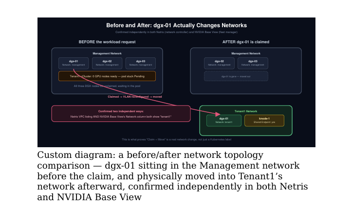
Checking the Management server cluster in the network controller
after the claim shows only the other two DGX nodes remain — dgx-01
is no longer there. Checking Tenant1’s own server cluster shows dgx
01 now listed under Tenant1’s VPC — not shared, not duplicated,
actually moved. The shared knode-1 endpoint from Module 3 still
shows up under Tenant1 too, still doing its job of being reachable from
multiple tenants without being fully owned by any one of them. Cross
checking against the hardware fleet manager is the final confirmation:
dgx-01’s network field now reads tenant1, while the other DGX nodes
still read management — the same physical inventory list, now showing
the live effect of one workload request.
The complete chain, end to end:
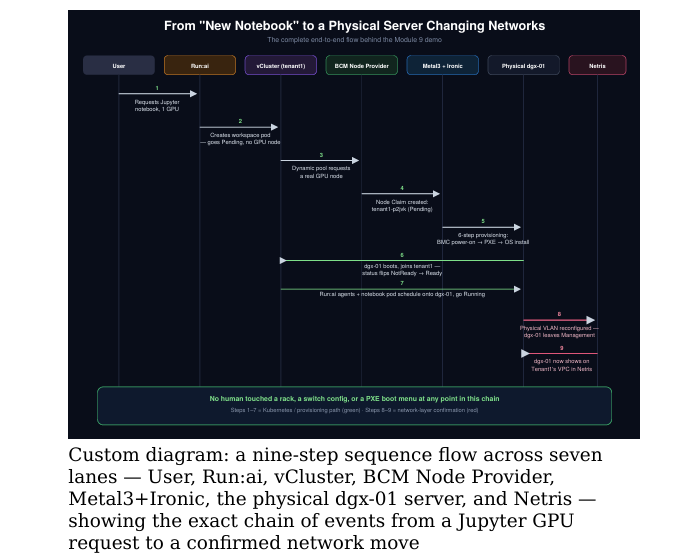
A user asked for a GPU notebook → Run:ai couldn’t schedule it → the
dynamic node pool asked BCM for a real bare-metal GPU server →
Metal3/Ironic provisioned it through the standard six-step flow → the
server joined the tenant’s Kubernetes cluster → the network was
reconfigured so that specific server now lives on the tenant’s isolated
VLAN instead of the shared management network → the notebook pod
scheduled and started running. No human touched a rack, a switch
config, or a PXE boot menu at any point in that chain. This is the single most useful diagram in this workbook for training
purposes — every other module explains one segment of this chain in
depth; this is the whole chain on one page.
Module 10: Key Takeaways
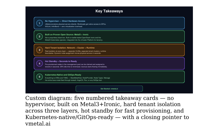
- No hypervisor — direct hardware access. vMetal provisions
physical servers directly. Workloads get native access to GPUs,
NVLink, and InfiniBand, with zero virtualization overhead. - Built on proven open source: Metal3 + Ironic. Not a
proprietary black box — battle-tested OpenStack Ironic and the
Metal3 Kubernetes operator, integrated with a tenancy and
lifecycle layer on top. - Hard tenant isolation: network + cluster + runtime. Real
isolation at every layer — separate VLANs, separate tenant
clusters, separate runtime boundaries. Dynamic node assignment
moves physical servers between tenant networks in seconds, as
you saw in Module 9. - Hot standby = seconds to ready. Pre-provisioned nodes in the
management pool can be claimed and assigned to tenants in
seconds. GPU idle time is minimized; revenue starts flowing
immediately. - Kubernetes-native and GitOps-ready. Everything is CRDs and
YAML — BareMetalHost, NodeProvider, Node Types. Manage the
entire bare-metal fleet through kubectl, ArgoCD, Flux, or any
GitOps tool you already run.
Glossary — Quick Reference
| Term | Meaning |
| BMC | Baseboard Management Controller — lets you remotely power-cycle and boot a server independent of its OS |
| Redfish / IPMI | Two protocols for talking to a BMC; Redfish is modern, IPMI is legacy |
| PXE boot | Booting a server over the network instead of from a local disk — how OS installation starts with no human present |
| Ironic | The engine that actually does BMC control, PXE orchestration, and OS installation |
| Metal3 | A Kubernetes operator that represents physical servers as Kubernetes objects |
| CRD | Custom Resource Definition — how Kubernetes lets you define your own object types |
| BareMetalHost | The Kubernetes object type (a CRD) representing one physical server |
| Hypervisor | Software that lets one physical machine run multiple virtual machines — deliberately absent from this stack |
| vCluster | A virtual, fully-isolated Kubernetes control plane running on top of a shared host cluster |
| KubeVirt | A way to run lightweight virtual machines on top of Kubernetes — used here only for non-GPU auxiliary nodes |
| VLAN / VXLAN | Network-layer isolation technologies used to keep tenants’ traffic separate |
| Node Claim | A request for a new node to join a tenant cluster, tracked separately from nodes that have already joined |
| Dynamic Pool vs Static Pool | Dynamic = provisioned on demand as workloads need capacity; Static = a fixed, always-present node |
Getting Started
If you want to try this hands-on without any physical hardware, local
testing is possible with KubeVirt alone (no bare metal needed) before
moving to a real BMC-backed environment. Full docs, local testing
instructions, and Certified Stack references are available at
vmetal.ai.
Conclusion: Building a Production-Ready Bare Metal GPU Cloud
Building a bare metal GPU cloud for NVIDIA DGX SuperPOD requires much more than installing GPUs and connecting high-speed networking.
A production environment also needs automated bare-metal provisioning, Kubernetes orchestration, tenant isolation, network segmentation, GPU scheduling, and lifecycle management.
Throughout this workbook, we followed that complete journey. We started with physical DGX infrastructure and explored how Metal3 and Ironic can automate bare-metal provisioning. Next, we examined how isolated Kubernetes environments and tenant networks can separate workloads.
Then, we followed dynamic node assignment from the shared hardware pool into a tenant environment. Finally, we saw how a GPU workload can trigger the provisioning of physical GPU capacity and ultimately run on the newly available infrastructure.
As a result, infrastructure teams can better understand how the different layers of a multi-tenant GPU cloud fit together—from hardware provisioning to workload execution.
Planning Your AI or GPU Infrastructure?
Moving from a proof of concept to production requires careful planning across GPU compute, high-performance networking, Kubernetes, security, tenant isolation, orchestration, and operations.
If your organization is planning or designing NVIDIA GPU infrastructure, Kubernetes GPU clusters, AI infrastructure, or enterprise data center environments, Trezbon can help you evaluate and design the supporting architecture.
Talk to Trezbon’s consultants:
https://trezbon.com/#contact
Continue exploring practical AI infrastructure and data center engineering guides on NetworkBachelor.
VMware NSX-T and Cisco ACI and Its Complimenting Use Cases

Arista Network Advantage: Lower TCO with Power-Efficient Platforms
AlgoSec – NSPM Solution Quick Review
About Author

abhishek
Expert in Network, Virtualization and Security field in On-Prem and Public Cloud. Passionate about new technology and consult the best solution to business organisation.Previously served Networkershome, EMC2, Cisco, VMware and Arista in different fields of Engineering, TAC, Consulting, Designing and Training. Certification : CCIE#48639, VCIX DCV and NV, Aviatrix Multi Cloud, SD-WAN Specialist, Palo Alto PCNSE, Amazon Cloud, Docker Certified Engineer. LinkedIn : https://www.linkedin.com/in/abhishekkunal51/