NSX-T Series: Part 13 – NSX-T EDGE Deploy Part-2
In this “NSX-T Series: Part 13 – NSX-T EDGE Deploy Part-2” part, we will discuss the difference between collapsed EDGE/Compute model and Non Collapsed. We will walk through the issue faced in Collapsed design and how to overcome from it.
If you want to start from beginning you can refer my previous part of the Series:
NSX-T Series : Part 1 -Architecture and Deploy
NSX-T Series : Part 2 – Adding Compute Manager
NSX-T Series : Part 3 – Planning NSX VXLAN
NSX-T Series : Part 4 – Transport Zones and Use cases for Multi-Transport Zone
NSX-T Series: Part 5 – NSX-T N-VDS and VDS 7.0
NSX-T Series: Part 6 – NSX-T Uplink Profile
NSX-T Series: Part 7 – NSX-T ESXi Transport Node
NSX-T Series: Part 8 – NSX-T Logical Switching Use Cases
NSX-T Series: Part 9 – NSX-T Logical Switching Services
NSX-T Series: Part 10 – NSX-T Routing
NSX-T Series: Part 11– NSX-T Multi-Tier Routing
NSX-T Series: Part 12 – NSX-T EDGE Deploy Part-1
Introduction
In this part we will discuss the task where we will discuss the location of EDGE deployment, which can be categorized as Collapsed and Non Collapsed design model. This all depends where you place your EDGE nodes.
It is very important to understand in NSX-T that there is no hard rule of preparing the host ( NSX-T VIB install and VTEP creation ), so to place EDGE VM over it. NSX-T Edges is independent of this model because EDGE maintains it’s own DVS within it called NDVS, which we discussed on our previous blog. As well as we need to consider EDGES as a separate Transport Node not like a vRouter which we used to consider in NSX-V.
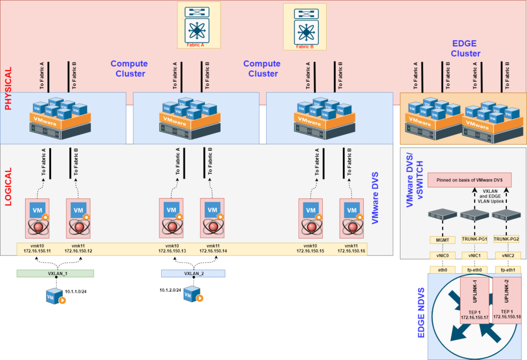
Collapsed Design
In this scenario we prepare all ESXi Hosts in Cluster with NSX-T VIBS which in result install VTEPs on all hosts ( depending on your uplink profile single or multi VTEP) and every host is ready to tag VXLAN header.
This design will be very ideal if the organization has less capacity of hosts and has small or mid sized Data Center
It further gives us opportunity to move VM and EDGE on any host and East-West and North-South traffic contains on same rack.
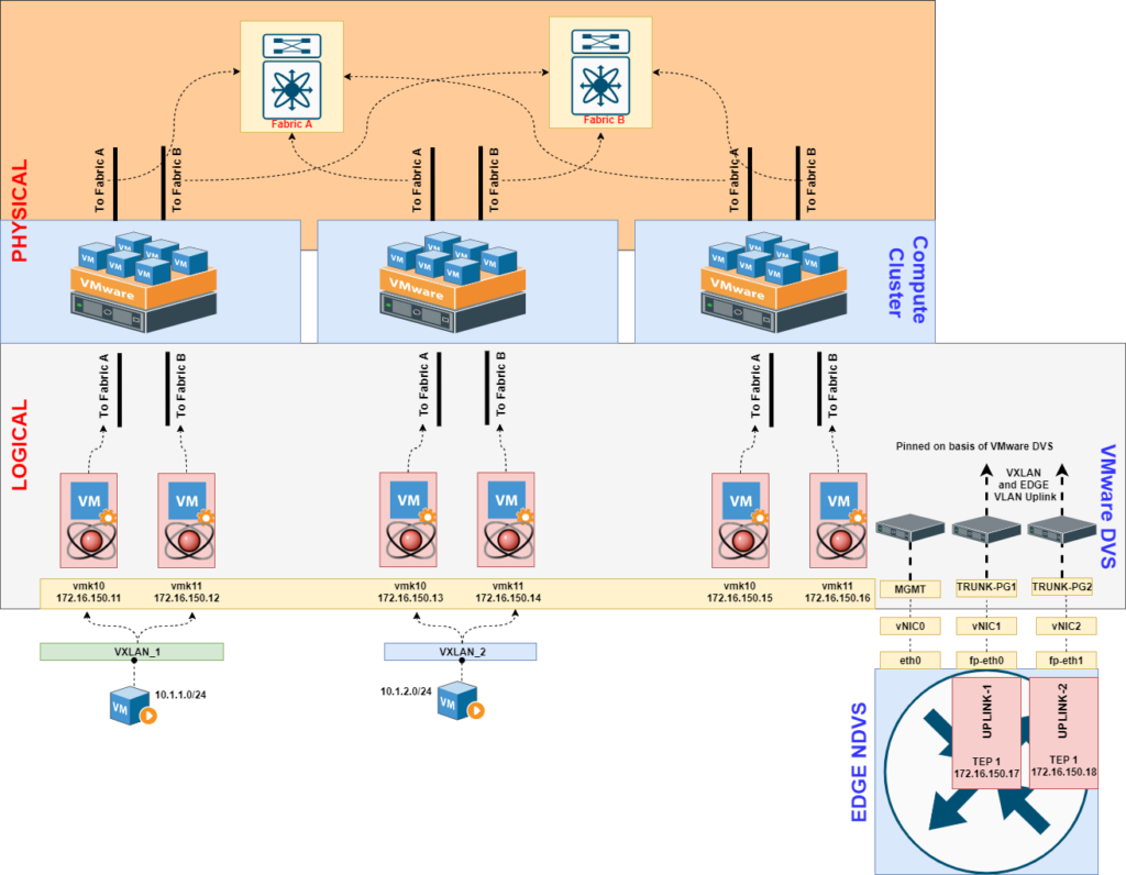
While implementing EDGE following points should be considered for both collapsed and non-collapsed environment :
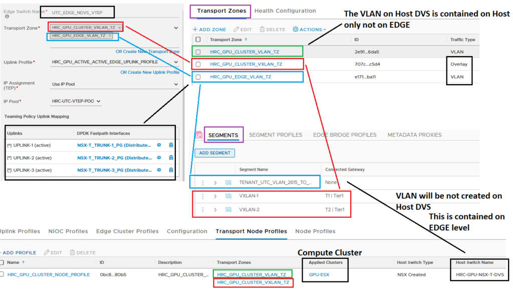
1. To create boundary of VXLAN ( which is extended between all host and EDGES ) : This is done via Transport Zone and host and prepared with this common VXLAN.
2. Contain the EDGE Uplink VLAN only on EDGE ( this is done by attaching the EDGE VLAN TZ ) : This makes sure we do not expose infra VLAN to EDGE level and Uplink VLAN on DVS Host level.
Silent Packet Drop : VTEP Tunnel Down Issue
This scenario is interesting and the logic lies on basic routing and switching and it comes when you place EDGE nodes on NSX-T prepared host.
As per the basic traffic flow in NSX-T we will witness VXLAN tagged traffic from ESXi Host to Edge in multiple scenario:
1. VXLAN attached VM to Edge Loopback ( This will be available on Edge T0-SR instance )
2. VXLAN attached VM to Uplink VLAN device
3. VLAN attached VM to other T0 router ( Inter SR routing )
4. VXLAN attached VM (1-T1) to VXLAN attached VM (2-T1) under same T0 this scenario will not create T0-DR instance on Host ( *** When T1 is attached to Edge Cluster for state full service***)
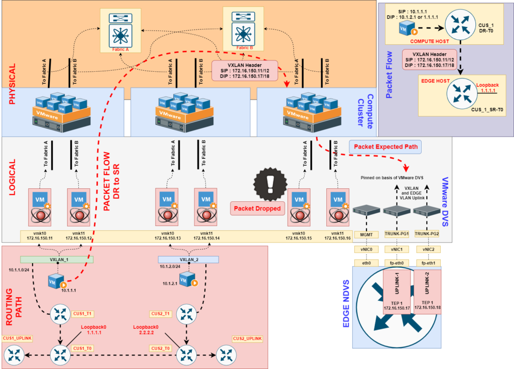
The traffic flow can be better visualized by following topology diagram, where VXLAN created by ESXi HOST ,which when it is reaches to the host where EDGE is deployed. This VXLAN encapsulated packet is silently dropped on ESXi Host as the destination ( VXLAN destined for EDGE VTEP) is on same subnet and Host assumes there is no IP residing on ESXi, even though it is alive on NSX-T Edge under N-DVS level.
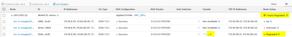
This scenario will alarm errors on ESXi nodes informing the nodes as “degraded”, because the VTEP tunnel between source ESXi Host and EDGE is not established.
Solutions:
To solve this issue design issue there could be 3 approaches which might us to get either more ESXi ( for separating EDGE Cluster in terms of ESXi: Collapsed Design ), or more Uplink ( for separating DVS/vSwitch for EDGE VM ) or Separate VLAN/Subnet for HOST TEP and EDGE TEP. This is all we discussed in following section:
1. Non Collapsed Design
This design requires separate EDGE Cluster in terms of ESXi ( non NSX-T prepared Host) and NSX-T prepared host. As we understood the issue is due to same subnet so if the Host where EDGE node resides that do not have NSX-T VXLAN VTEP, this solves the issue.
This design will require separate rack for EDGE ESXi and that might be possible for big Organization. Another benefit of this design is the UPLINK VLAN is contained on the EDGE ESXi rack , and not required to be extended on NSX-T prepared host. ( Though the best practice from NSX-T config should be followed which we discussed on above section of Collapsed Design )
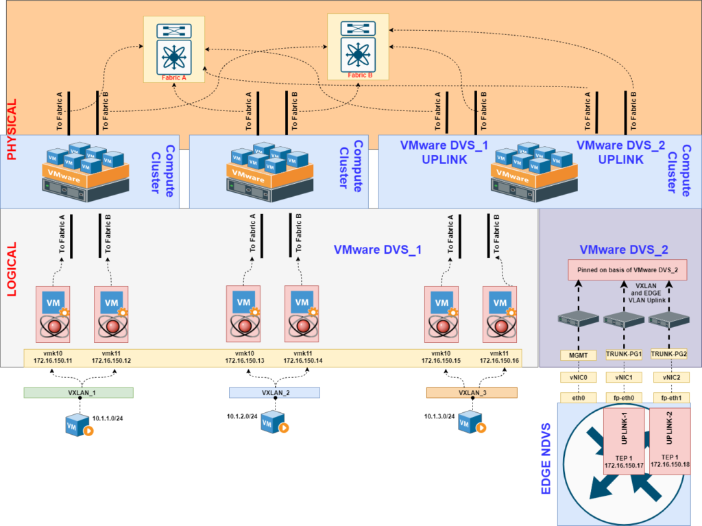
3. Separate DVS/vSwitch for EDGE VM
This could be another tricky method to solve the issue where if the host has more Physical Uplink we can create separate DVS/vSwitch for the traffic of EDGE VM. This will well require more uplinks from physical level and the UPLINK for EDGE will contain only VXLAN and Uplink VLAN traffic.
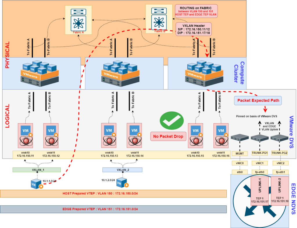
3. Separate VLAN/Subnet for HOST TEP and EDGE TEP
This method will solve the issue in terms of routing rather switching. If we separate Host TEP and Edge TEP VLAN/Subnet , the host which used to drop packet of Edge TEP this time it will witness destination traffic for other subnet. So this makes Host TEP to send traffic to Infra Router to route the traffic between Host TEP and Edge TEP.
In this method the major requirement to double check the supported MTU of Infra Router and match according to NSX-T VXLAN MTU.
Summary
In this blog, we discussed the difference between collapsed EDGE/Compute model and Non Collapsed. We will walked through the issue faced in Collapsed design and how to overcome from it by Non Collapsed, Separate Uplink DVS/vSwitch and Separate VLAN/Subnet option. For further refrence please follow VMware document.
In further blog we will discuss the packet walk of NSX-T in terms of SR and DR. I would like to thanks for visiting my blog. Happy Learning!
NVIDIA GPU Workloads on Kubernetes — Part 11: Key Concepts Deep Dive
NVIDIA GPU Workloads on Kubernetes — Part 4: Adding GPU Worker Nodes
NVIDIA GPU Workloads on Kubernetes — Part 9: Observability Stack for GPU Clusters
About Author
abhishek
Expert in Network, Virtualization and Security field in On-Prem and Public Cloud. Passionate about new technology and consult the best solution to business organisation.Previously served Networkershome, EMC2, Cisco, VMware and Arista in different fields of Engineering, TAC, Consulting, Designing and Training. Certification : CCIE#48639, VCIX DCV and NV, Aviatrix Multi Cloud, SD-WAN Specialist, Palo Alto PCNSE, Amazon Cloud, Docker Certified Engineer. LinkedIn : https://www.linkedin.com/in/abhishekkunal51/
well explained sir,
Legend!