NSX-T Series: Part 12 – NSX-T EDGE Deploy Part-1
In this “NSX-T Series: Part 12 – NSX-T EDGE Deploy Part-1” part, we will discuss the modes of EDGE that can be deployed for NSX-T and different design for EDGE which could be single NDVS and Multi NDVS design. In further blog we will discuss the Collapsed and Non Collapsed design.
But if you want to start from beginning you can refer my previous part of the Series:
NSX-T Series : Part 1 -Architecture and Deploy
NSX-T Series : Part 2 – Adding Compute Manager
NSX-T Series : Part 3 – Planning NSX VXLAN
NSX-T Series : Part 4 – Transport Zones and Use cases for Multi-Transport Zone
NSX-T Series: Part 5 – NSX-T N-VDS and VDS 7.0
NSX-T Series: Part 6 – NSX-T Uplink Profile
NSX-T Series: Part 7 – NSX-T ESXi Transport Node
NSX-T Series: Part 8 – NSX-T Logical Switching Use Cases
NSX-T Series: Part 9 – NSX-T Logical Switching Services
NSX-T Series: Part 10 – NSX-T Routing
NSX-T Series: Part 11– NSX-T Multi-Tier Routing
NSX-T EDGE Node Form Factors
Firstly it is very important to understand the deployment method of NSX-T Edge, which could be categorized in 2 ways :
1. VM Form Factor ( VM on ESXi host ) : This is one of the common used methods where we can spin the EDGE as per our need, this is gives the elasticity in the architecture. The elasticity can be defined in terms of onboarding multi-tenant customers and defining separate EDGES as well as scaling the datacenter as per the ECMP traffic needs.
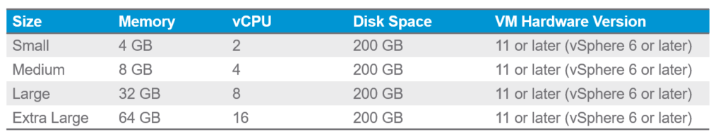
The VM form factor EDGE can be deployed by choosing the following deployment size:
2. Bare Metal Node : This method requires certified Bare metal hardware where the EDGE kernel can be installed, and by following the required steps it can be onboarded to NSX-T Manager. This method is mostly suited if you are aware about the amount of traffic expected and could be installed without dependency of ESXi as Virtual layer.
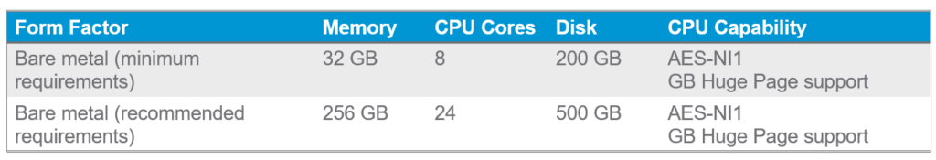
The following are the form factors that can be choose:
NSX-Edge Deployment
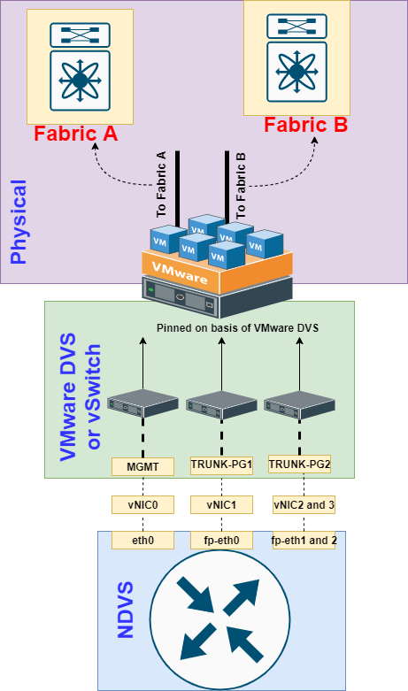
It is very important to understand in NSX-T the EDGE functions has gone on EDGE Virtualization level, where we need visualize that there is always an DVS as like how we see on ESXi. Though it looks like a black box, but we will witness router container service will be instantiated on the Edges.
So whenever we deploy Edge on ESXi, one must visualize that we are going to play with kind of Nested ESXi setup.
We believe we have done a lot labs on Nested ESXi and we define the Parent ESXi port-group in such manner so we uplink the traffic from child ESXi to outside the network.
So in simple language it is “NDVS over DVS or vSwitch over Network“
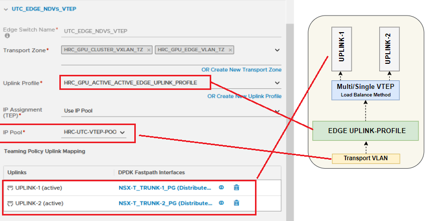
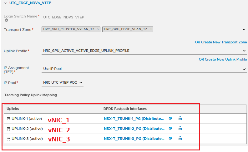
To deploy Edge from NSX-T manager we need to define the following parameters:
1. Edge Uplink Profile ( this will define single TEP or multi TEP design, with respect to load balance method and Transport VLAN for TEP),
2. IP Pool for TEP ( In Edge/Compute Collapsed design always define separate subnet for TEP for EDGE and Host, will discuss further on blog we will discuss why it is required)
3. Transport Zone ( Best practice is to extend VXLAN and Edge Uplink VLAN )
4. Uplink ( Choose the Uplink and map to correct VC defined Port-Group or NSX-T Defined VLAN Segment )
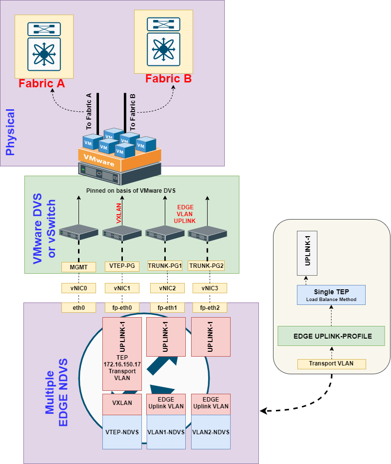
Multiple NDVS Design
Prior to 3.0 version we did not had option to map VXLAN and Edge Uplink VLAN on single NDVS, so in simple way every uplink ( vNic ) of Edge needed separate NDVS so to map respective function.
Though this method is also being followed to utilize all the vNic of the EDGE VM for the traffic and it gives us option to either have multiple TEP or multiple Uplink EDGE Vlan. The following topology shows the single TEP and multiple VLAN Uplinks.
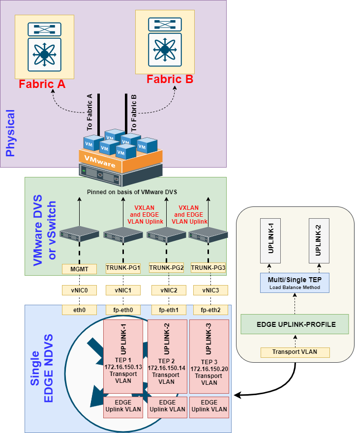
Single NDVS Design
With NSX-T 3.0 we now have option to map VXLAN and Edge VLAN Uplink on single NDVS, this saves us to configure multiple NDVS. Though following in this method we can utilize all vNIC of the EDGE VM and we can see witness 3 TEP bind to respective NIC.
This option will give us the more load-balance Hash option and same interface can be used for VLAN extension too.
This implementation can be easily understood by following topology diagram:
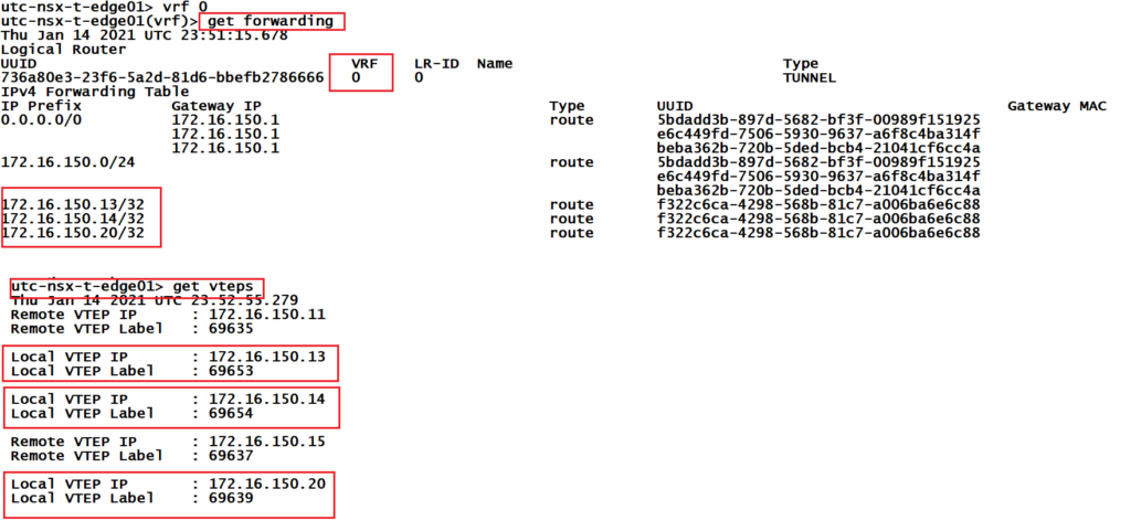
And when you login on NSX-EDGE after it is powered on one can check following verification commands to check TEP configured. I would suggest to follow the new updates of EDGE Design on VMware Blog site.
Summary
In this blog, we discussed the types of Edge which could be VM over ESXi or could be Bare metal. As well as we understood the difference between Single and Multiple NDVS design. In further blog we will discuss the design aspect of EDGE in Collapsed and NON Collapsed model. I would like to thanks for visiting my blog. Happy Learning!
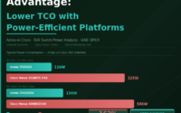
Arista Network Advantage: Lower TCO with Power-Efficient Platforms
VMware vSAN Solution Analysis
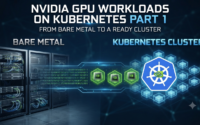
NVIDIA GPU Workloads on Kubernetes — Part 3: What Happens Inside the Cluster After Operators Deploy
About Author
abhishek
Expert in Network, Virtualization and Security field in On-Prem and Public Cloud. Passionate about new technology and consult the best solution to business organisation.Previously served Networkershome, EMC2, Cisco, VMware and Arista in different fields of Engineering, TAC, Consulting, Designing and Training. Certification : CCIE#48639, VCIX DCV and NV, Aviatrix Multi Cloud, SD-WAN Specialist, Palo Alto PCNSE, Amazon Cloud, Docker Certified Engineer. LinkedIn : https://www.linkedin.com/in/abhishekkunal51/
Your Blogs are Super helpfull. Thankyou. It’s just like bible for NSX. Thankyou
multiple links are not working.