NSX-T Series: Part 17 – NSX-T Segment T1 and T0 on same Edge Cluster T0 as SR
Introduction
In this part we will explore the traffic behavior and design option when a NSX-T Segment which is attached to T1 Gateway and T1 and T0 are mapped to same Edge Cluster. We will split the scenario into 2 sub category where in this blog post we will go through when T0 has only the SR service.
If you want to start from beginning you can refer my previous part of the Series:
NSX-T Series : Part 1 -Architecture and Deploy
NSX-T Series : Part 2 – Adding Compute Manager
NSX-T Series : Part 3 – Planning NSX VXLAN
NSX-T Series : Part 4 – Transport Zones and Use cases for Multi-Transport Zone
NSX-T Series: Part 5 – NSX-T N-VDS and VDS 7.0
NSX-T Series: Part 6 – NSX-T Uplink Profile
NSX-T Series: Part 7 – NSX-T ESXi Transport Node
NSX-T Series: Part 8 – NSX-T Logical Switching Use Cases
NSX-T Series: Part 9 – NSX-T Logical Switching Services
NSX-T Series: Part 10 – NSX-T Routing
NSX-T Series: Part 11– NSX-T Multi-Tier Routing
NSX-T Series: Part 12 – NSX-T EDGE Deploy Part-1
NSX-T Series: Part 13 – NSX-T EDGE Deploy Part-2
NSX-T Series: Part 14 – NSX-T Segment without IP Subnet/Gateway
NSX-T Series: Part 15 – NSX-T Segment with T1 Gateway without EDGE Cluster
NSX-T Series: Part 16 – NSX-T Segment T1 Gateway with EDGE Cluster(SR)
Scenario 4.1 : T0 and T1 on same Edge Cluster ( T0 has the SR service )
From our previous understanding we are aware about the difference between T0 and T1, and it’s capability of connecting the physical network to virtual infra. Where T0 gives the option of connecting to uplink network either with the help of static or dynamic routing (BGP or OSPF as per 3.1.2 release ).
We can club both T0 and T1 mapped to same cluster which is logically possible, and in that case the for both T0 and T1 DR service will be instantiated across the transport node ( as per the participating VM ). The SR service will be only available on Edge as per the service enablement. In the following topology we will see the Routing feature as SR service but same concept can be followed if we have other services.
DR-SR Topology
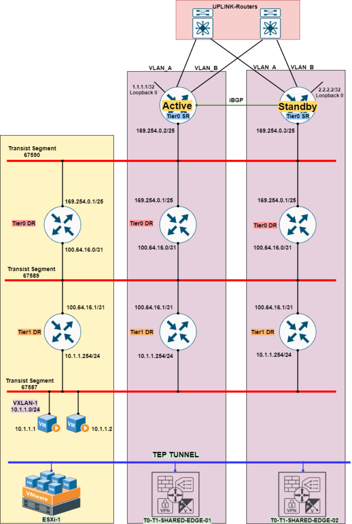
In the above topology it is important to understand the service enablement on different component and auto plumbing to transist vxlan. On the ESXi layer which will handle DR service which will have both T0 and T1 DR, and same parallel setup will be auto created on Edge Cluster.
The Edge Cluster will have both T0 and T1 DR service, and as in our consideration T0 will function for uplink routing then in that case it will also have SR service. ( If we enable SR service on T1, T1 SR component will be created which we will discuss on scenario 4.2 in other post ).
As we aware it is T1 which connects to T0 northbound so same visualization should be made in our mind, so it become easy to understand the traffic flow. The basic fundamental which should be followed which is “Routing to the Nearest”
Traffic to North
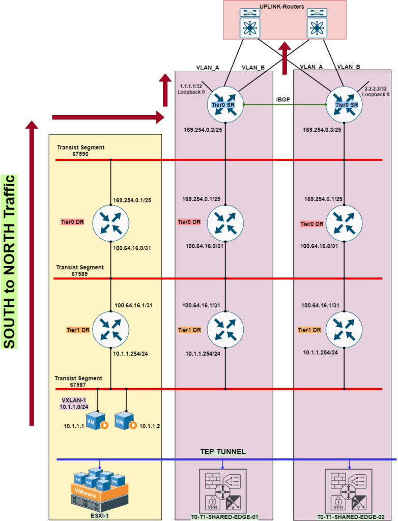
The traffic pattern will be in manner what we discussed in above section, where the routing will occur until the last available component which in this case ESXi will route until T0-DR.
After ESXi T0-DR the traffic will be tunneled to Active Edge to it’s SR component which will further route traffic to Uplink router.
Traffic to South
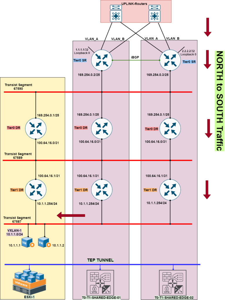
Traffic from Uplink router will hit to Active Edge to it’s SR component and move the traffic to it’s other component, but as per previous scenario ( South to North ) this time the routing for T1 will be taken care by Edge itself.
The traffic will be routed on Edge from T0-SR—> T0-DR—> T1-DR and through tunneled traffic, it will reach the destination VM hosted on ESXi.
Design Decision
>> In this scenario of 4.1 ( T0 and T1 on same cluster ) T0 with SR, we need to understand what service is enabled if it is routing only in that case one should choose Active-Active mode( This gives us opportunity to use the system to the highest level)
>> When we configure Active-Active Mode we need to make sure resiliency on network layer should be enabled, with the collaborative feature of dynamic routing with process like BFD/Graceful restart.( this all depends what device capability on Uplink)
>> An Active-Active Edge cluster cannot be changed to Active-Standby until you do not delete the related component to function it as a single entity.
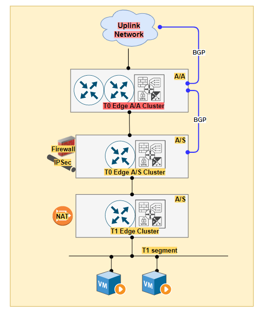
>> When we have requirement to have Stateful services ( Firewall, NAT and IPSec) we need to choose cluster to be in Active/Standby mode. ( This will give us opportunity to use only one Edge at a time and in that case it is recommended to deploy high form factor Edge, so it can occupy the Data Plane Traffic ).
>> The topology could be also to have multiple Edge Cluster of T0 ( first layer for Active-Active ) next T0 ( Active-Standby for Statefull service ) and further T1 as DR component ( can be SR also ) We will discuss this kind of scenario on next post.
Summary
In this blog, we covered the scenario where we have both T0 and T1 on same Edge cluster and understood the traffic flow with design decision. In our next post we will discuss when we have SR service on T1 on same Edge cluster of T0.
Thanks again for visiting the Blog. Happy Learning.

The NVIDIA Switch Field Guide: Models, NVUE CLI, and Protocol Support

The Questions No Single Team Can Answer

NVIDIA GPU Workloads on Kubernetes — Part 9: Observability Stack for GPU Clusters
About Author
abhishek
Expert in Network, Virtualization and Security field in On-Prem and Public Cloud. Passionate about new technology and consult the best solution to business organisation.Previously served Networkershome, EMC2, Cisco, VMware and Arista in different fields of Engineering, TAC, Consulting, Designing and Training. Certification : CCIE#48639, VCIX DCV and NV, Aviatrix Multi Cloud, SD-WAN Specialist, Palo Alto PCNSE, Amazon Cloud, Docker Certified Engineer. LinkedIn : https://www.linkedin.com/in/abhishekkunal51/
Hello
I think that t0 on top of t0 topology not supported now on nsx-t 3.2 right?
Correct me please
hi. thanks for sharing very simple and step by step explain nsx-t. part 6 is not available. could you fix it or correct it?
Hi,
Is it possible to map 2 x Edge Clusters (Tier 0s for north-south routing) to same overlay transport zone? Thanks.
– part 6 is gone, points to the same as 8, part 6 is completely gone
– part 8 links are bad, points to the same as 6, can be reached via main page
– part 11 links are bad, and points to 10, can be reached via main page
in the case of nat and t0, if traffic goes from tenant-A t1 to tenant-B t1. it goes up to tier0-DR. But what if traffic needs to be SNAT’ed before reaching tenant-B? How does NSX know it needs to send traffic via tier0-SR to nat it before that?
Hi,
Any plans to fix part 6 links ?
This is quality work regarding the topic! I guess I’ll have to bookmark this page. See my website UQ8 for content about Cosmetic Treatment and I hope it gets your seal of approval, too!