NSX-T Series: Part 14 – NSX-T Segment without IP Subnet/Gateway
Introduction
In this part we will discuss the different scenario of routing in NSX-T and will go through the detailed analysis of NSX-T DR and SR components of routing. We will check the traffic path for East-West and North-South.
In this part we will focus on Segment without IP Subnet/Edge Cluster scenario.
We will try to split this section in multiple parts where we will go through the scenario of Segment with/without gateway and EDGE Cluster, SR instance placement in regards to T1, and it’s traffic pattern. So it is very important to understand the routing table of DR/SR instances. So let’s explore with different scenarios.
If you want to start from beginning you can refer my previous part of the Series:
NSX-T Series : Part 1 -Architecture and Deploy
NSX-T Series : Part 2 – Adding Compute Manager
NSX-T Series : Part 3 – Planning NSX VXLAN
NSX-T Series : Part 4 – Transport Zones and Use cases for Multi-Transport Zone
NSX-T Series: Part 5 – NSX-T N-VDS and VDS 7.0
NSX-T Series: Part 6 – NSX-T Uplink Profile
NSX-T Series: Part 7 – NSX-T ESXi Transport Node
NSX-T Series: Part 8 – NSX-T Logical Switching Use Cases
NSX-T Series: Part 9 – NSX-T Logical Switching Services
NSX-T Series: Part 10 – NSX-T Routing
NSX-T Series: Part 11– NSX-T Multi-Tier Routing
NSX-T Series: Part 12 – NSX-T EDGE Deploy Part-1
NSX-T Series: Part 13 – NSX-T EDGE Deploy Part-2
LAB Layout
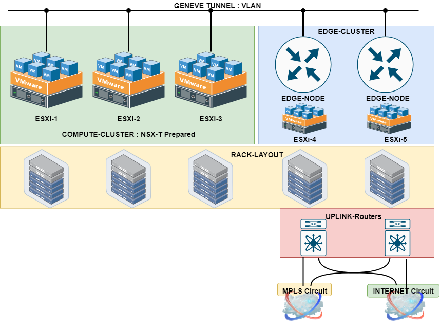
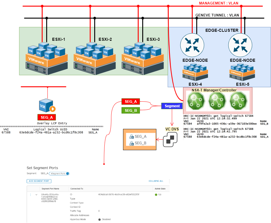
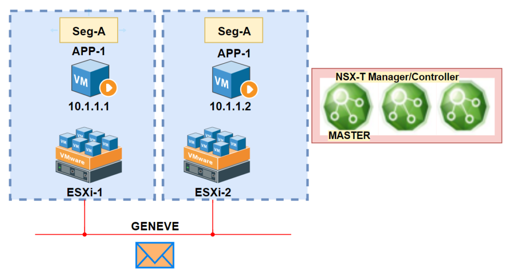
To demonstrate all scenarios let’s understand the LAB setup where I have following setup :
1. 5 ESXi are added in the VC Cluster
2. 5 ESXI are prepared with NSX-T VIBS ( Will consider first 3 ESXi as Compute Cluster )
3. 2 ESXi will host the EDGE* ( Have separate DVS for EDGE TEP Traffic, so will consider ESXi4 and ESXi5 as EDGE ESXi Cluster )
Scenario 1 : Segment without IP Subnet/Edge Cluster
In this scenario we will witness the concept of Realized and Unrealized state of NSX with Infra. This mechanism looks to the infra changes which could be addition/removal/vmotion of the VM from one host to other. So to explain further if you create a segment and there is no VM going to use it, then in that situation the segment won’t be pushed from the controller to ESXi host.
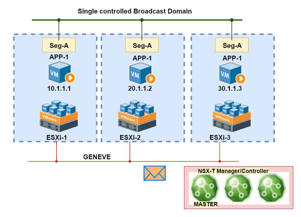
In below scenario:
Segment SEG_A is created T1 Gateway: NO and IP Subnet: NO
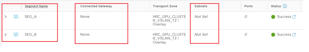
Realized State
The segment can be viewed on NSX-Manager/Controller and VC but not on ESXi Nodes, until no VM is not attached to that logical switch from VC.
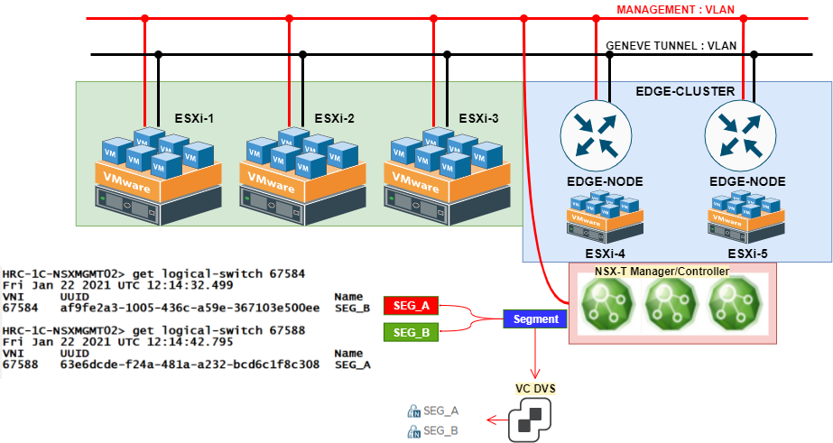
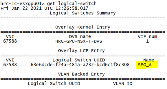
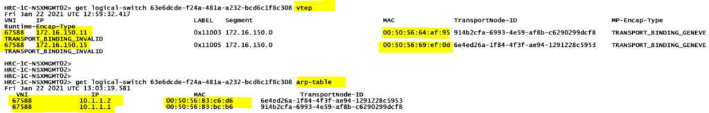
As soon as we add the VM on ESXi-1 ( where VM resides) we witness the VXLAN is being advertised from NSX Manager which can be seen via “get logical-switches” ( The same step can be visualized for VM2 which could reside on ESXi2, and only SEG_B will be advertised on ESXi2)
Logical Router
In this scenario if we do not have Logical router so won’t be able to reach to other subnet, because we will not see DLR will be created on any of the ESXi instances.
Logical Switching
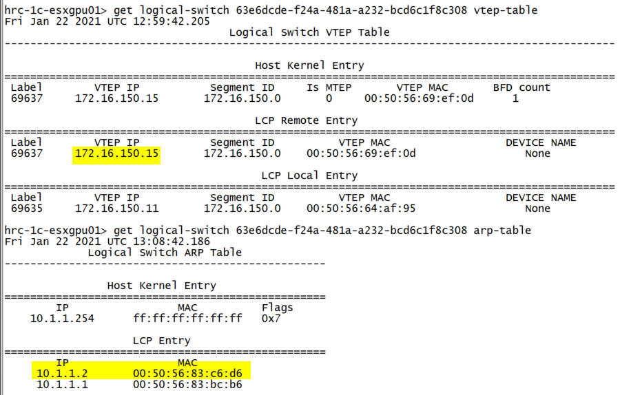
In this scenario we will witness how the ESXi VTEP Table is created and traffic is instantiated from VM1 to VM2 which is connected on SEG_A.
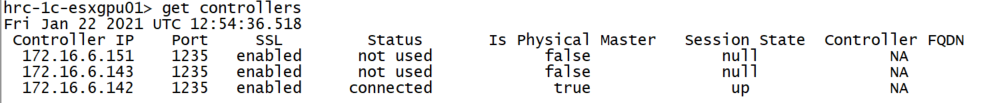
ESXi to Controller Channel: Every ESXi will maintain CCP connection to Controller ( Among 3 one will be elected as MASTER ) and this channel is used to get the update of the end-point detail, if any of the end-point (VM) want to communicate to it.
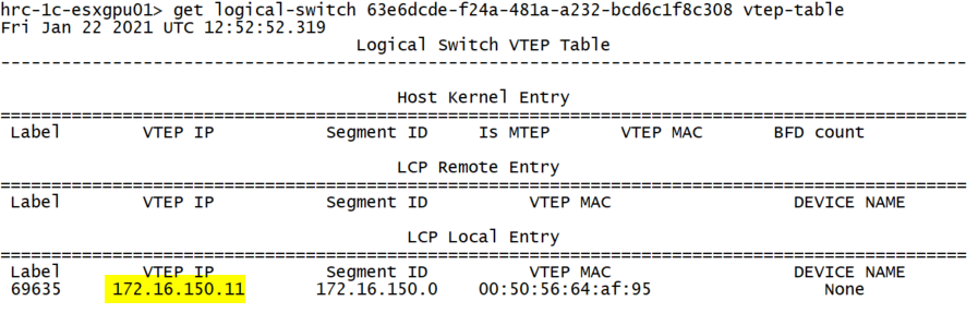
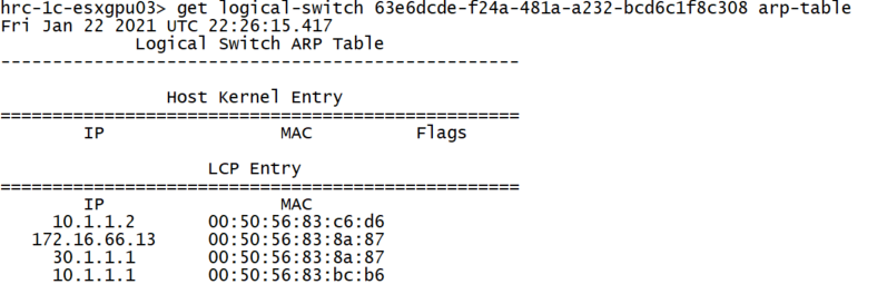
The information on arp-table is passed to Controller and local ESXi on the basis of single vtep/multi-vtep config will perform load-sharing which we can see on ESXi VTEP Table.
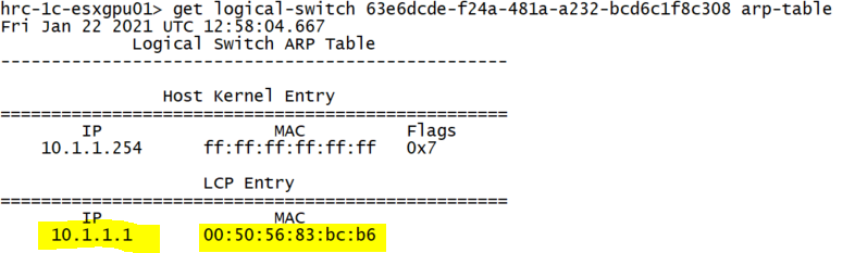
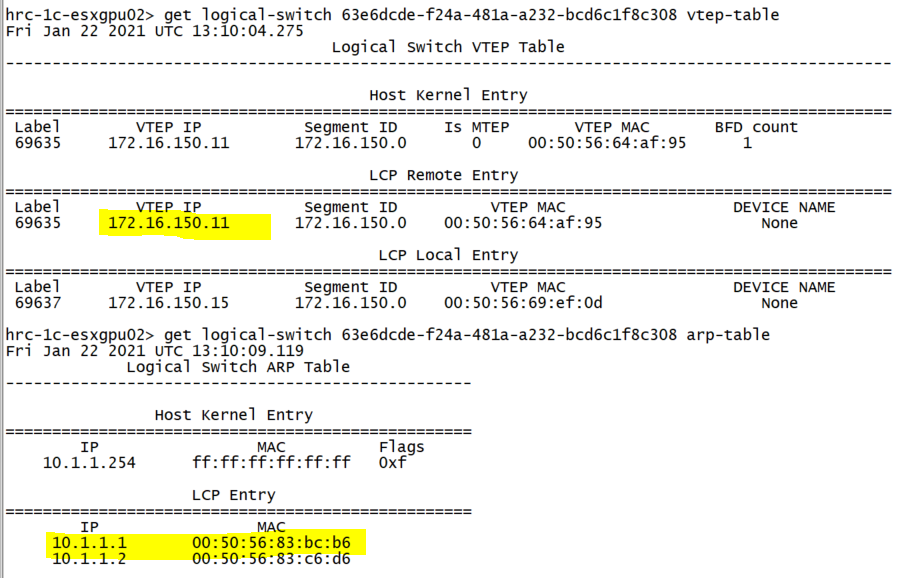
Controller Sync : If VM2 ( 10.1.1.2 ) is connected on ESXi-2 on same SEG_A, then the similar table will be witnessed on ESXi2 ( except VTEP Table : There the update of the each other VM on same segment detail will be published via Controller ). This is all scenario where we save ourself from flood and learn situation.
Controller make ESXi-1 amd ESXi-2 realize the VM of same Segment ( VXLAN ). True SDN!
And the same is also updated on ESXi-1 and ESXi-2
Use Case : Scenario 1
This scenario can be used where the broadcast domain will be defined on the basis of L3 subnet of the VM.
The VM’s learned on this segment will be irrespective of their L3subnet.
This can be compared to Cisco ACI where a EPG attached to a Bridge-Domain ( without VRF and gateway) and the end points can be containerized on L3 basis. As an example in our scenario we connected 3 VM on different subnet and still the MAC was learned.
Summary
In this blog, we started to discuss the NSX Realized State and under Routing Scenario, we touch the base on the elementary level where we have Segment without IP Subnet/Edge. This scenario is simple Logical Switching and gives the end-point on same IP Subnet and Segment to communicate with each other even though on different ESXi. For more reference we can follow VMware config guide.
In further blog we will discuss the Scenario 2 : Segment with Gateway without EDGE Cluster.
From Business Requirement to Production LLM: A Full-Cycle Scenario
The Questions No Single Team Can Answer
NSX-T ALB AVI Series : Part01
About Author
abhishek
Expert in Network, Virtualization and Security field in On-Prem and Public Cloud. Passionate about new technology and consult the best solution to business organisation.Previously served Networkershome, EMC2, Cisco, VMware and Arista in different fields of Engineering, TAC, Consulting, Designing and Training. Certification : CCIE#48639, VCIX DCV and NV, Aviatrix Multi Cloud, SD-WAN Specialist, Palo Alto PCNSE, Amazon Cloud, Docker Certified Engineer. LinkedIn : https://www.linkedin.com/in/abhishekkunal51/