NSX-T Series: Part 15 – NSX-T Segment with T1 Gateway without EDGE Cluster
Introduction
In this part we will continue the discussion of connecting the segment with T1/T0 Gateway and will explore option of Cluster requirement. We will look the design case where this can be applied in the real scenarios.
If you want to start from beginning you can refer my previous part of the Series:
NSX-T Series : Part 1 -Architecture and Deploy
NSX-T Series : Part 2 – Adding Compute Manager
NSX-T Series : Part 3 – Planning NSX VXLAN
NSX-T Series : Part 4 – Transport Zones and Use cases for Multi-Transport Zone
NSX-T Series: Part 5 – NSX-T N-VDS and VDS 7.0
NSX-T Series: Part 6 – NSX-T Uplink Profile
NSX-T Series: Part 7 – NSX-T ESXi Transport Node
NSX-T Series: Part 8 – NSX-T Logical Switching Use Cases
NSX-T Series: Part 9 – NSX-T Logical Switching Services
NSX-T Series: Part 10 – NSX-T Routing
NSX-T Series: Part 11– NSX-T Multi-Tier Routing
NSX-T Series: Part 12 – NSX-T EDGE Deploy Part-1
NSX-T Series: Part 13 – NSX-T EDGE Deploy Part-2
NSX-T Series: Part 14 – NSX-T Segment without IP Subnet/Gateway
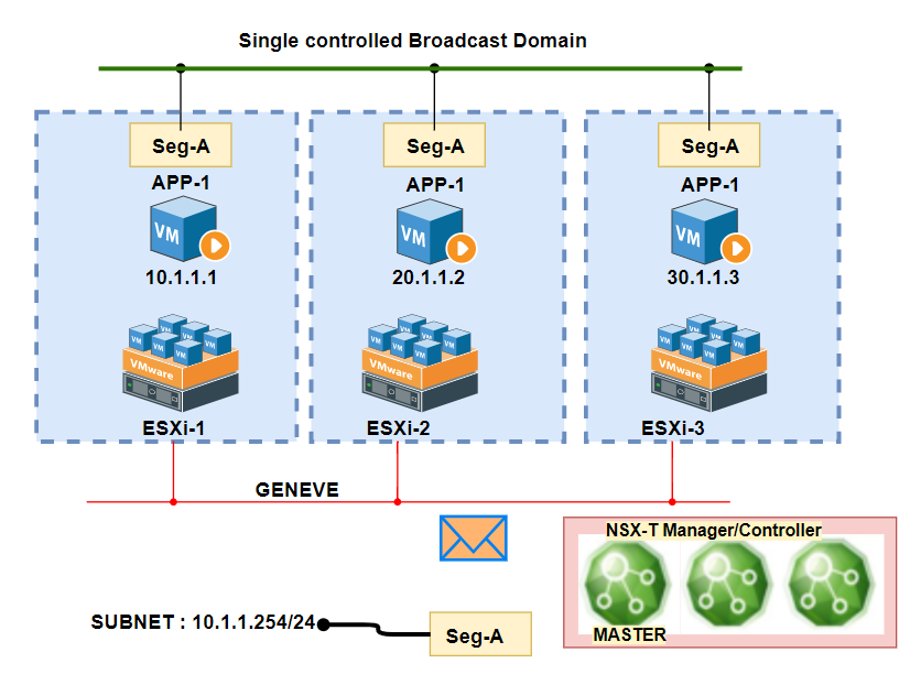
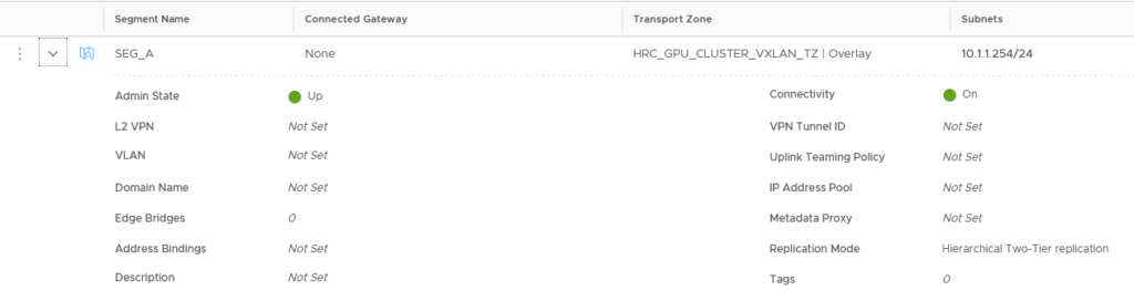
Scenario 2 : Segment with IP Subnet without Gateway(T1/T0):
When I initially started I though to skip this section with later though to include, though this do not make major difference in the behavior to Scenario1 which we discussed in our previous post.
Even though we add the subnet for Segment, the gateway IP will be not live until it is not attached to any Gateway (T0/T1), but exception will be when you terminate L2VPN.
So keep in mind while terminating L2VPN for this VXLAN double check the IP otherwise there could be issue DUP-IP.
Scenario 3 : Segment with IP Subnet attached to Gateway T1
In our previous series Part-10 and 11 we discussed in detail the difference between T0 and T1 and what is Single Tier and Multi Tier routing. I would suggest to revisit it. In this scenario we will solely focus on the route table update process.
Design Consideration with T0/T1
But before implementing we need touch the fllowing basic points T0/T1:
>> T0 can provides single Tier routing and segment can be directly connected
>> T0 can be Active-Active ( if statefull service like NAT and Firewall not being used ), and if State full service need to used then Active-Standby need to be choosed
>> T1 are always Active-Standby.
>> T0 can’t connect to another T0 directly ( that requires Uplink router communication
>> Multiple T1 can be connected to T0 ( considering T1 as per Tenant or per Environment [Prod,Dev,Test] environment.
>> T1 can be connected to single T0 at a time.
>> Each T1 can have overriding IP subnet to other T1, in that case NAT can be used to distinct the traffic. ( Will discuss this scenario in further blogs )
>> SR services is instantiated if the Central service is required.
>> There are many other points need to re-visit while creating LB as service for T1 and T0, totally depends on the releases.
Scenario 3.1 T1 without Edge Cluster
While creating T1 we get option of choosing EDGE-Cluster, usually this option should be chosen if the Stateful Service like NAT/Firewall need to be used.
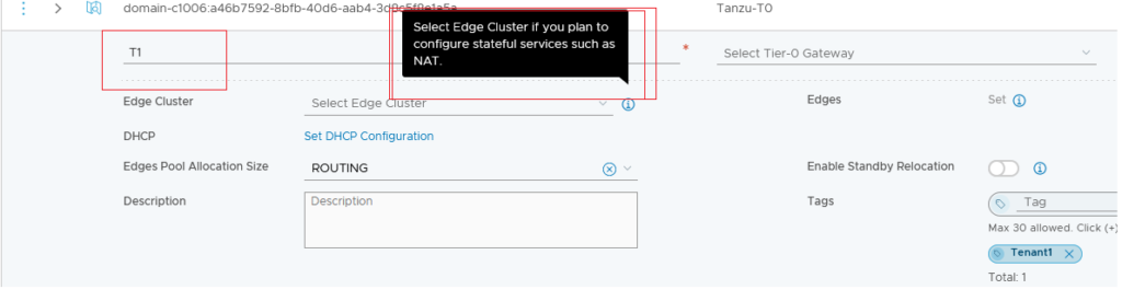

The moment we added segment to T1, the VM was reachable to subnet gateway which we created in Scenario 2.

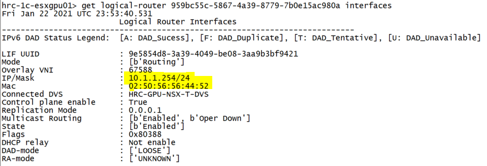
DR Logical Router instantiated:
When the T1 is created and it instantiates DR service on Compute nodes where the Segment VM is available ( On the basis of realization )

Let’s add another segment SEG_B and connect VM2 with 10.1.2.0/24 ( Gateway as 10.1.2.254 )
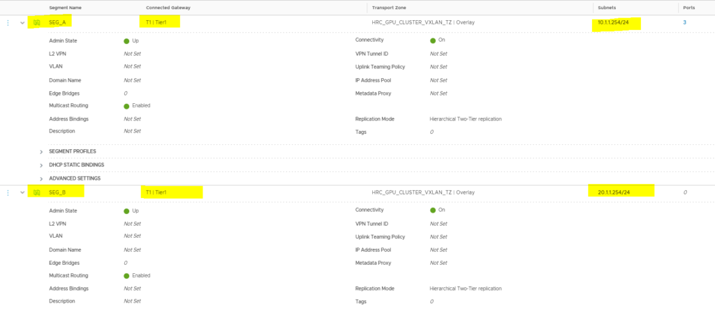
Topology : T1 without Edge Cluster
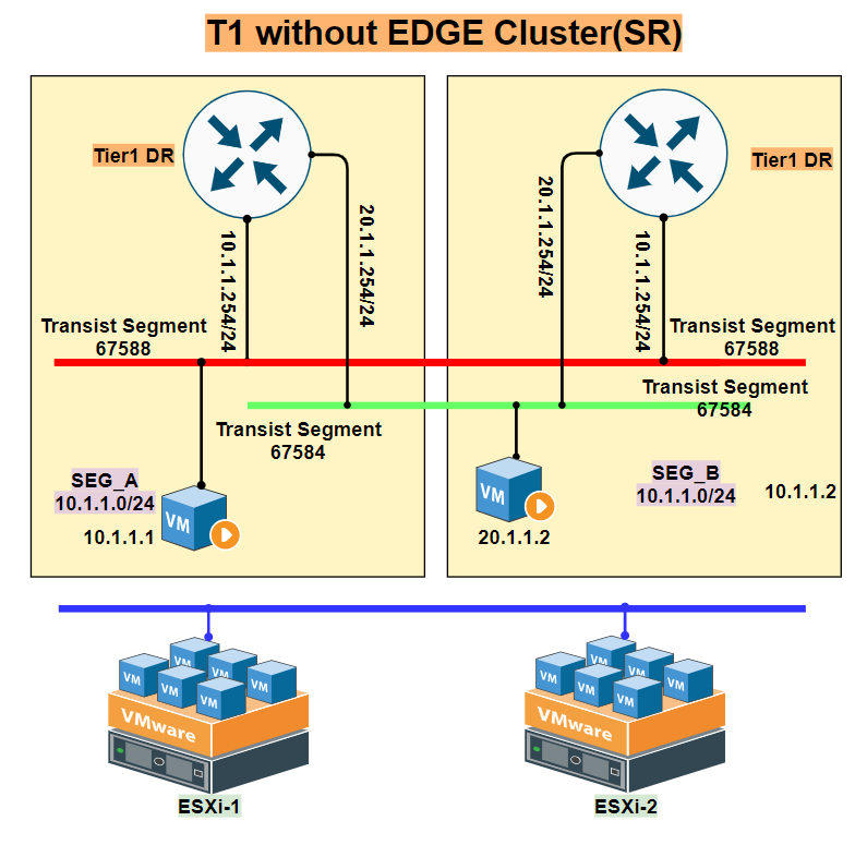
T1 without Edge cluster is design where only T1-DR instance will be instantiated but no SR capability can be used which includes Statefull service like NAT, IPsec, etc. So if the VM is mostly for routing/switching service inside the Compute Node, it is recommended to not attach Edge Cluster.
The same can be viewed in following topology, I would recommend to visualize this diagram on your mind because further the other component when added the service will keep on getting added. The same applies for T0 Gateway also.
This addition quickly updates the routing table for T1-DR instance :
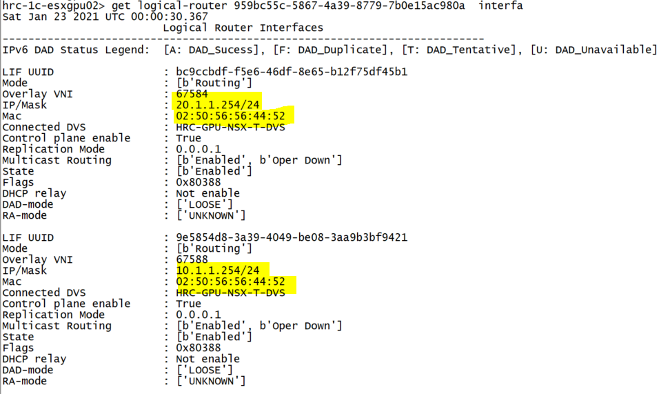
ANYCAST-GATEWAY: If you will look closely the MAC of the DR interface (02:50:56:56:44:52) remains same on every interface and on other host also, this can be considered as similar concept of “Anycast-Gateway” in Cisco ACI or other native VXLAN solutions. The endpoint VM assume it is single router as gateway.
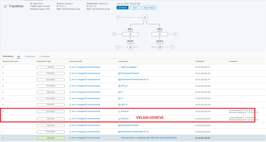
VXLAN Routing : As like many vendors NSX follows Route-Bridge-Route path and always consider route near source concept.

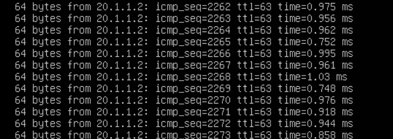
Packet Trace
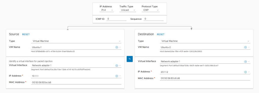
Summary
In this blog, we covered the basic of Distributed router and verified how the T1-DR is instantiated and makes routing under the ESXi kernel. This method do not require any kind of EDGE VM and traffic is East-West which is processed by DLR kernel of NSX-T. For more reference we can follow VMware config guide.
In next blog we will see the consequence of adding Edge Cluster on T1 and will verify the traffic flow. I would like to thanks for vesting the site.

Building the Backend: AI Fabric Design from Scalable Units to Lossless RoCEv2
VMware vSAN Solution Analysis
vCloud Director: NSX-V to NSX-T Migration Part-2
About Author

abhishek
Expert in Network, Virtualization and Security field in On-Prem and Public Cloud. Passionate about new technology and consult the best solution to business organisation.Previously served Networkershome, EMC2, Cisco, VMware and Arista in different fields of Engineering, TAC, Consulting, Designing and Training. Certification : CCIE#48639, VCIX DCV and NV, Aviatrix Multi Cloud, SD-WAN Specialist, Palo Alto PCNSE, Amazon Cloud, Docker Certified Engineer. LinkedIn : https://www.linkedin.com/in/abhishekkunal51/
Hi Abhishek,
The NSX-T Series: Part 6 – NSX-T Uplink Profile seems to have disappeared – URL is faulty?
Best series on NSX-T
Regards
Robert
Thanks Robert… for your comment… great to hear it is useful.
Regarding Part 6 we will re create it..
Hello Abhishek,
As per my knowledge, NSX-T utilize GENEVE as a encapsulation protocol and NSX-V use VXLAN. You are talking about VXLAN routing in NSX-T topic. I don’t understand this. Am I missing something?
Hi Abhishek,
The IPs shown in the first picture of this blog, 10.1.1.1, 20.1.1.2 and 30.1.1.3, shouldn’t be 10.1.1.1, 10.1.1.2 an 10.1.1.3 because the VMs are in the same segment?
Regards.